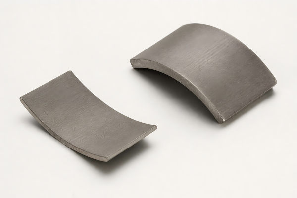
External Profiles
Contour plates, precision inserts and shaped components with a defined datum reference and controlled release sequence.

Ningbo Vanguard Technologies Co., Ltd
Precision profiles, narrow slots and hardened tooling, engineered around your drawing.
Vanguard supports custom wire electrical discharge machining for conductive metal components, tooling and assembly fixtures. From prototype contours to repeat production, we review the material, cut path, workholding and inspection requirements before machining.
Define the critical geometry first. Wire size, entry access, thickness and finishing passes determine the practical process window.

Process Selection
Wire EDM removes conductive material by controlled electrical discharges between a moving wire and the workpiece. It is useful where hard material, fine contours or tool access make conventional machining difficult.
The process avoids conventional cutting-tool pressure, but it is not free of thermal effects or distortion. Residual stress, flushing, part support and surface requirements still need an engineering review.
Service Scope
Choose the cutting strategy around the drawing, not a general accuracy claim.
Contour plates, precision inserts and shaped components with a defined datum reference and controlled release sequence.
Through openings and narrow features with an entry hole or an accessible edge for wire threading.
Hardened tooling profiles with mating clearance, corner relief and surface condition specified before cutting.
Angled cuts and draft features reviewed against thickness, guide clearance and the required top and bottom geometry.
Locating nests, conductive pole pieces, carriers and gauge profiles for component development and assembly.
Drawing review, sample validation and a repeatable cutting and inspection plan for agreed production quantities.
Project Workflow
Maintain one datum scheme and one agreed finished-part specification.
Confirm material grade, thickness, heat treatment, critical contours and inspection requirements.
Plan clamping, start holes, rough stock allowance and any stress-relief sequence.
Define wire compensation, entry paths, taper, finishing passes and slug retention.
Execute the approved rough and skim-cut strategy with suitable flushing and support.
Verify profile, dimensions, orientation and surface condition using suitable measurement methods.
Clean parts and apply the agreed corrosion protection, identification and packaging.
Drawing Requirements
Feasibility and achievable tolerances are confirmed for the actual material, thickness and geometry.
| Feature | Specify in the RFQ | Process Consideration | Acceptance Focus |
|---|---|---|---|
| Profile Cutting | 2D contour, datums and profile tolerance | Wire compensation and finishing strategy | Profile relative to functional datums |
| Internal Window | Entry location, opening size and corner radius | Start hole and slug removal access | Window size, corner form and position |
| Narrow Slot | Width, depth through stock and end radius | Wire diameter, discharge gap and flushing | Slot width and wall form |
| Taper Cut | Angle, reference plane and upper/lower contours | Thickness and guide clearance | Taper and dimensions at defined planes |
| Hardened Tooling | Grade, hardness and heat-treatment condition | Residual stress and cut sequence | Geometry after final release |
| Surface-Critical Part | Roughness and surface integrity criteria | Skim cuts and any approved post-treatment | Specified finish and surface condition |
DFM Priorities
Resolve these four issues before releasing the cutting program.
Kerf depends on wire diameter and the discharge gap. Inside corners have a finite radius; perfectly sharp internal corners are not a standard wire EDM outcome. Review relief features where mating geometry requires them.
A closed internal contour needs a threading hole or another suitable entry. Conventional wire EDM cuts through the workpiece; blind pockets generally require a different process.
Plan tabs, retention and cut order so released slugs cannot damage the part. Thin sections and heat-treated stock may move when material is removed.
Define roughness and any recast-layer restrictions for loaded or fatigue-sensitive features. Skim passes and approved finishing operations must be selected for those requirements.
Material Review
Electrical conductivity is essential; material condition also affects the cutting and protection plan.
Review hardness, prior heat treatment, residual stress and corrosion protection, especially for slender punches and inserts.
Confirm grade and finished surface requirements. Profile tolerance and thickness guide the finishing strategy.
Review the carbide grade and binder system, edge strength and surface integrity before quoting fine or loaded features.
Conductive nonferrous parts can be considered with a material-specific cutting and workholding plan.
Confirm material certification needs and any restrictions on the EDM surface for the intended application.
Steel pole pieces and conductive carriers are candidates. Permanent magnets need a separate review of conductivity, thermal sensitivity, corrosion and final magnetic properties. Most ferrites and plastics are unsuitable for conventional wire EDM.
Quality Planning
Agree on measurement methods and reporting requirements before sample production.
| Control Area | What Can Go Wrong | Verification Approach |
|---|---|---|
| Profile & Position | Correct local dimensions but incorrect datum relationship | Optical or coordinate measurement aligned to specified datums. |
| Taper & Straightness | Dimensions vary through the material thickness | Measure at defined planes with a method suitable for the geometry. |
| Corners & Slots | Radius or slot width prevents assembly | Profile inspection and agreed functional checks. |
| Surface Condition | Finish or recast condition does not suit service loading | Roughness measurement and additional surface evaluation where specified. |
| Released Geometry | Part moves after the final cut or unclamping | Inspect the finished, released part in the agreed condition. |
| Cleanliness & Protection | Debris, staining or corrosion affects assembly | Visual checks and agreed cleaning and preservation requirements. |
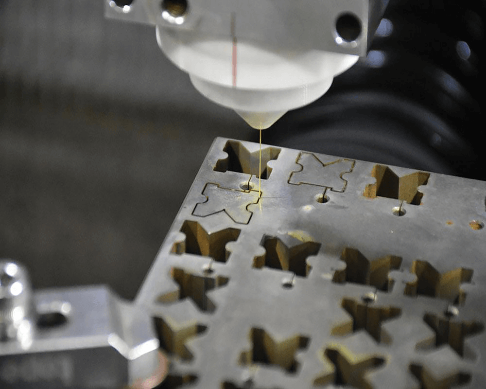
Process References
Reference photos illustrate wire guides and workpiece setups, not Vanguard equipment ownership.
RFQ Preparation
Provide the finished-part requirements along with the geometry.
Revision-controlled 2D drawing, DXF or other contour data, 3D model where needed, thickness and critical datums.
Grade, hardness, heat treatment, supplied stock condition and any requirements for material documentation.
Profile limits, corner radii, taper, surface roughness, surface integrity criteria and inspection report needs.
Prototype and batch quantities, forecast volume, supplied-part scope, packaging and target delivery date.
Engineering Questions
Send your drawing for a feature-by-feature process review.
Contact VanguardConventional wire EDM requires electrically conductive material. Steel, many nonferrous alloys and conductive carbide grades can be reviewed; hardness alone does not establish suitability.
A closed internal profile normally needs an entry hole for threading the wire. An open contour may allow entry from an edge. The starting method must suit the part and machine setup.
No. The wire diameter and discharge gap impose a minimum practical internal radius. A smaller wire or an approved corner-relief feature may help meet the mating requirement.
Standard wire EDM is a through-cutting process. Blind cavities usually require milling, sinker EDM or another suitable process.
Yes, conductive hardened parts are common candidates. Heat-treatment distortion, residual stress and final release movement still need to be considered.
Both are confirmed after reviewing thickness, material, geometry, quantity and inspection scope. Tight profile tolerances may require additional skim passes and validation rather than a blanket accuracy commitment.
Share the drawing, material, thickness and quantity for a practical manufacturing review.