Ningbo Vanguard Technologies Co., Ltd
FEA Simulation for Motor and Magnetic Assembly Development
Finite element analysis support for engineering teams that need to review stress, deformation, thermal behavior, magnetic field distribution, vibration risk and production reliability before tooling, prototyping or mass production.
Engineering Positioning
Simulation Should Answer a Real Design Question
FEA is valuable when the model, load case and acceptance criteria are connected to the actual engineering decision. Vanguard uses simulation as a design review tool for motor components, magnetic assemblies and production-oriented mechanical structures.
We support customers that need to check whether a rotor sleeve is strong enough, whether a magnet bonding design has enough margin, whether a stator or housing will overheat, whether a shaft will deform, or whether a magnetic circuit has saturation or leakage risk.
The goal is not to create decorative color plots. The goal is to reduce prototype risk, define inspection priorities and guide practical design changes before cost has already been locked into tooling or production.
Service Snapshot
What We Help Engineering Teams Evaluate
01 Structural Safety Stress, displacement, contact pressure, safety factor and weak areas in shafts, sleeves, housings, brackets and magnet retaining structures.
02 Thermal Behavior Heat source, conduction path, temperature rise, cooling path, adhesive or magnet temperature limit and housing heat dissipation.
03 Magnetic Field Flux density, air-gap field, leakage flux, magnetic force, saturation risk, magnet utilization and basic motor magnetic circuit behavior.
04 Design Iteration Comparison of geometry, material, magnet layout, sleeve thickness, cooling strategy, gap tolerance or assembly process options.
Image Gallery
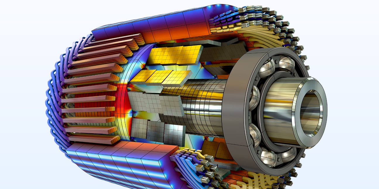
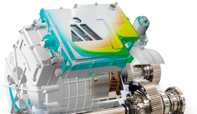
Typical Simulation Visuals for Motor Development


Engineering Intake
Information Needed for a Serious FEA Review
Simulation quality depends on input quality. Geometry alone is not enough; load cases, constraints, material data and acceptance criteria must be defined so the result can be interpreted correctly.
| Input Area | Recommended Data | Why Engineers Need It | Typical Output |
|---|---|---|---|
| Geometry Model | STEP, STP, IGS, X_T, assembly model or production drawing | Defines the simulation domain, contacts and critical features | Cleaned model and setup direction |
| Material Data | Elastic modulus, yield strength, density, thermal conductivity, magnet grade | Controls stress, deformation, thermal and magnetic result accuracy | Material assumption list and risk notes |
| Load Conditions | Force, torque, pressure, speed, centrifugal load, thermal load, magnetic force | Determines whether the simulation matches the actual working condition | Defined load case matrix |
| Boundary Conditions | Mounting points, bearing positions, bonding areas, shrink fit or sleeve interface | Boundary assumptions strongly affect stress and deformation results | Constraint and contact definition |
| Acceptance Criteria | Safety factor, max deformation, allowable temperature, flux target, stress limit | Allows results to be judged instead of only visualized | Pass/fail review and improvement direction |
| Validation Reference | Test data, failed sample, measured temperature, torque-speed data or inspection data | Helps calibrate assumptions and interpret result reliability | Simulation-to-test comparison notes |
Workflow
How an FEA Simulation Project Usually Moves Forward
1 Question Definition Confirm what the simulation must answer: strength, deformation, temperature, flux, vibration, contact or failure risk.
2 Model Preparation Clean geometry, simplify non-critical details, define materials, contacts, constraints and load cases.
3 Mesh & Solve Generate mesh, refine critical areas and check whether the result behavior is physically reasonable.
4 Result Review Review stress, displacement, temperature, flux density, safety factor or frequency against criteria.
5 Design Feedback Recommend geometry, material, process, assembly or test changes based on simulation findings.
Simulation Scope
FEA Simulation Types We Can Support
Structural Stress Analysis Static strength, deformation, safety factor, contact pressure, weak point identification and thickness optimization.
Rotor High-Speed Review Centrifugal stress, sleeve retention, magnet bonding risk, shaft stress, overspeed condition and rotor safety.
Thermal Heat Transfer Temperature rise, cooling path, housing conduction, potting effect, winding temperature and magnet temperature risk.
Magnetic Field Simulation Flux density, magnetic leakage, air-gap field, saturation, magnetic force, Halbach array and motor circuit review.
Design Choices
Typical Engineering Trade-Offs
Simulation should support engineering judgment. A very detailed model is not always better if the load conditions are uncertain; a simplified model can be valuable when it is tied to a clear decision.
For motor and magnetic assembly projects, Vanguard can help review whether the model detail, material assumptions, load cases and validation plan match the level of decision being made.
Deliverables
What Customers Can Receive
Setup Simulation Assumption Notes Geometry assumptions, material data, load cases, boundary conditions and contact definitions.
Results FEA Result Plots Stress, displacement, safety factor, temperature, flux density, magnetic force or modal results as applicable.
Action Design Recommendations Thickness change, radius change, material change, magnet layout change, cooling path or retention improvement.
Comparison Design Version Review Side-by-side comparison of multiple design versions, materials, dimensions or operating conditions.
Risk Weak Area Summary Overload risk, thermal hot spots, saturation areas, deformation concerns and boundary limitations.
Prototype Validation Guidance Recommended inspection points, test conditions and design features that should be validated physically.
Risk Control
Common FEA Simulation Risks We Check Early
Boundary Unrealistic Constraints Over-constrained or incorrectly fixed models can make stress and deformation results misleading.
Material Unknown Data Generic material data may not represent actual molded, cast, magnetic, laminated or heat-treated materials.
Load Case Missing Operating Conditions Products often fail under peak load, thermal expansion, vibration, assembly stress or overspeed conditions.
Mesh Weak Mesh Sensitivity Stress concentration areas need proper mesh refinement before making final design decisions.
Manufacturing Ignoring Variation Tolerances, runout, adhesive thickness, shrinkage and assembly gaps can change real performance.
Validation No Physical Reference FEA reduces risk, but prototype testing is still important for final engineering confidence.
FAQ
FEA Simulation FAQ
Can FEA replace prototype testing?
No. FEA is best used to reduce design risk, compare design options and define what should be tested. For production approval, physical validation is still important.
Can you review rotor sleeve and magnet retention risk?
Yes. Rotor stress, sleeve retention, magnet bonding area, centrifugal load, overspeed condition and temperature margin can be reviewed before prototype build.
Do you support magnetic field simulation?
Yes. We can support magnetic circuit review for permanent magnet motors, magnetic assemblies, Halbach arrays, magnetic couplings and magnet layout comparisons.
What files should we send first?
The best starting package is a 3D model, drawing, material data, load case, boundary condition, target result, acceptance criteria and any existing test or failure data.
Send Us Your Model, Load Case or Current Failure Problem
Useful files include STEP/STP models, drawings, material data, operating conditions, speed, temperature, test data, failed sample photos and the engineering question you need the simulation to answer.
Image sources: Hero and 3D motor simulation images from COMSOL motor modeling resources; permanent magnet motor structure interaction image from COMSOL documentation; magnetic flux density image from EOT case material; rotor structure analysis image from EnginSoft. Images were selected from visible no-watermark web results. For formal commercial publishing, please confirm usage rights with the source owners or replace them with company-owned simulation images or project visuals.
Engineering Services
Set A Consultation Today
Name can't be empty
Email error!
Send Your Message
*We respect your confidentiality and all
information are protected.