
High-Speed Motor Engineering
Segmented NdFeB Magnets for Reducing Eddy Current Loss
A practical guide to segmentation direction, insulated interfaces, rotor retention and validation for lower magnet heating in high-speed permanent magnet motors.
Why solid rotor magnets can become a heat source
Time-varying magnetic fields from stator slotting, inverter harmonics and spatial flux harmonics can induce circulating currents inside electrically conductive NdFeB magnets. Those currents generate heat directly in the rotor, where cooling is often more difficult than in the stator.
As electrical frequency, harmonic content and rotor speed increase, magnet eddy-current loss can reduce efficiency and raise local magnet temperature. Excessive temperature may weaken adhesive, increase sleeve stress and reduce demagnetization margin. Dividing one large magnet into electrically insulated segments shortens available current paths and can materially reduce this loss.
Magnets and rotor structures affected by segmentation choices
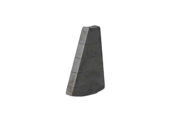
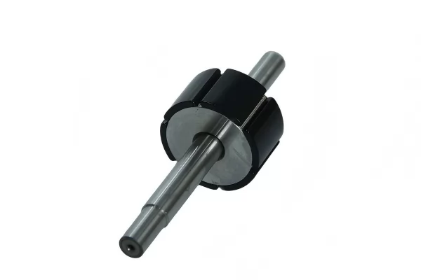
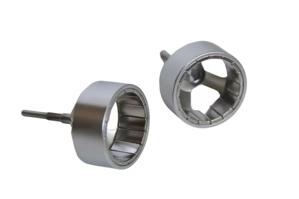
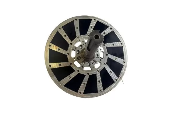
Segmentation must interrupt the dominant current loop
Identify harmonics
Review slotting, PWM switching, winding distribution, pole count and operating-speed range.
Map current paths
Use electromagnetic analysis to locate magnet regions and directions with concentrated induced current.
Divide electrically
Split the magnet in the direction that shortens the harmful loop and insulate adjacent pieces.
Validate thermally
Confirm that reduced magnet loss produces an acceptable temperature under the real duty cycle.
Important: More segments do not automatically create the best motor. Every additional interface affects magnet volume, assembly time, tolerance stack, adhesive exposure and mechanical retention. The optimum count is a system-level tradeoff.
Common segmentation strategies
| Strategy | Typical Purpose | Advantages | Engineering Attention |
|---|---|---|---|
| Monolithic magnet | Lower-frequency or cost-sensitive motors | Simple geometry, fewer bondlines and fast assembly | Potentially long conductive paths and higher harmonic loss. |
| Axial segmentation | Long rotor magnets divided along stack length | Shortens axial current paths and supports modular assembly | Axial positioning, cumulative gaps and end retention. |
| Circumferential segmentation | Wide arc magnets or large rotor diameter | Reduces tangential current-loop dimensions | Pole coverage, angular tolerance, adhesive joints and torque ripple. |
| Thin laminated slices | High electrical frequency and demanding loss target | Strong electrical subdivision in a compact final envelope | Insulation integrity, handling, bondline control and cost. |
| Multi-direction segmentation | Complex 3D harmonic paths or axial-flux rotors | Targets more than one current-loop direction | Part count, fixture complexity, tolerance stack and retention. |
Four design points that determine whether segmentation works
Electromagnetic model
A loss study should include operating speed, current waveform, PWM strategy, slotting and temperature-dependent material data. A simplified sinusoidal model may miss the dominant harmonic source.
Electrical insulation
Adjacent pieces need a stable insulating interface. Adhesive coverage, coating condition, squeeze-out and conductive debris can create unintended current bridges.
Mechanical retention
Segmented magnets still experience centrifugal and thermal loads. Sleeve preload, adhesive shear, rotor geometry and overspeed requirements must be checked as one system.
Magnetic performance
Inter-segment gaps reduce active magnet volume and may change local flux. Magnet grade, segment count and joint thickness should be optimized together.
From individual slices to a production-ready rotor
Recommended verification points
| Control | What It Confirms | Typical Method | Production Note |
|---|---|---|---|
| Segment dimensions | Fit, active magnet volume and joint consistency | CMM, profile measurement or dedicated gage | Measure features that locate the segment in the assembly fixture. |
| Polarity and orientation | Correct magnetic direction for every piece | Polarity indicator, Hall probe or mapping fixture | Use error-proof marking and sequence control. |
| Bondline coverage | Mechanical integrity and electrical separation | Process records, witness samples or agreed NDT | Define adhesive volume and cure window. |
| Assembled runout | Air-gap clearance and sleeve concentricity | Indicator, roundness equipment or CMM | Reference the functional shaft or bearing datum. |
| Dynamic balance | Mass distribution at operating speed | Two-plane balancing where applicable | Balance after final retention features are installed. |
| Thermal performance | Actual loss-reduction benefit | Motor test, temperature sensors and calibrated duty cycle | Compare like-for-like cooling and operating conditions. |
Where low-loss segmented magnets are most valuable
High-speed spindle motorsElectric compressorsTraction motorsHigh-frequency servo motorsAxial-flux motorsFlywheel systemsVacuum pump motorsAerospace electric machines
Information needed for a segmented magnet review
Segmented NdFeB magnet questions
Does segmentation always reduce magnet eddy-current loss?
It is effective when the split interrupts the dominant induced-current path and adjacent pieces remain electrically isolated. The result should be confirmed by electromagnetic and thermal analysis for the actual motor waveform.
How many magnet segments are required?
There is no universal number. The optimum depends on electrical frequency, harmonic spectrum, magnet dimensions, loss target, joint thickness, assembly cost and mechanical-retention requirements.
Do adhesive joints reduce motor torque?
Bondlines replace a small amount of active magnet volume and can affect local flux. A thin, controlled interface is therefore included in the magnetic model and tolerance analysis.
Can SmCo magnets also be segmented?
Yes. SmCo can be segmented or laminated for high-temperature, high-frequency applications, but its brittleness requires suitable handling, geometry and assembly controls.
Can Ningbo Vanguard supply complete segmented rotor assemblies?
Yes. Ningbo Vanguard Technologies Co., Ltd can support magnet selection, segmentation review, prototype magnets, fixture bonding, sleeve integration, runout and balance inspection, and production-oriented rotor assembly control.
Engineering Support
Reduce rotor heating without losing control of manufacturability
Send your motor data, rotor drawing, magnet grade, operating speed and current segmentation concept. Our team can review the magnetic, thermal and assembly implications from prototype through production.


