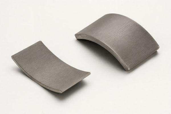
Grade Selection
Balance remanence, intrinsic coercivity, operating temperature, magnetic circuit and cost. Chinese Y and American C grades are listed below.
Ningbo Vanguard Technologies Co., Ltd
Cost-effective ceramic block magnets for motors, speakers, magnetic separation, holding and sensing applications.
Vanguard supports grade selection, block geometry, magnetization planning, sample development and production supply. Dimensions, working gap, steel circuit and acceptance method are reviewed together for reliable performance.
Request a Drawing Review
Selection Snapshot
Balance remanence, intrinsic coercivity, operating temperature, magnetic circuit and cost. Chinese Y and American C grades are listed below.
Specify length, width, thickness, chamfers, edge condition, holes or slots and dimensional datums.
Define thickness, length or width magnetization with a polarity sketch. The shape alone does not identify the pole faces.
Request bare magnets, polarity-sorted sets, adhesive-backed parts or assembly support after feasibility review.
Geometry & Magnetization
Use a dimensioned drawing rather than relying only on the words block or bar. Mark functional faces, chamfers, grinding direction and any restricted edge chips.
State the required pole faces, magnetization direction and marking method. Include the test surface and orientation when specifying surface flux.

Engineering Selection
Holding force or flux depends on grade, dimensions, pole area, steel return path, air gap and mating surface. Select the block as part of the complete circuit.
Thickness in the magnetization direction influences the operating point. Review the load line and temperature-dependent curves rather than selecting by surface flux alone.
Sintered ferrite is hard and brittle. Add suitable chamfers, avoid point loading and define acceptable chips on functional and nonfunctional edges.
Define bond-line clearance, surface preparation, cure conditions and mechanical support. Magnets should not be forced into an interference fit without a specific validated design.
Magnetic Performance
Reference values at 20 °C from the existing Vanguard ferrite grade table. The approved material specification and agreed inspection criteria govern each order.
| Grade | Standard | Br mT | Br kG | Hcb kA/m | Hcb kOe | Hcj kA/m | Hcj kOe | BHmax kJ/m³ | BHmax MGOe |
|---|---|---|---|---|---|---|---|---|---|
| Y8T | Chinese | 200-235 | 2.0-2.35 | 125-160 | 1.57-2.01 | 210-280 | 2.64-3.52 | 6.5-9.5 | 0.8-1.2 |
| Y10T | Chinese | 200-235 | 2.0-2.35 | 128-160 | 1.61-2.01 | 210-280 | 2.64-3.52 | 6.4-9.6 | 0.8-1.2 |
| Y20 | Chinese | 320-380 | 3.2-3.8 | 135-190 | 1.70-2.39 | 140-195 | 1.76-2.45 | 18.0-22.0 | 2.3-2.8 |
| Y22H | Chinese | 310-360 | 3.1-3.6 | 220-250 | 2.76-3.14 | 280-320 | 3.52-4.02 | 20.0-24.0 | 2.5-3.0 |
| Y23 | Chinese | 320-370 | 3.2-3.7 | 170-190 | 2.14-2.39 | 190-230 | 2.39-2.89 | 20.0-25.5 | 2.5-3.2 |
| Y25 | Chinese | 360-400 | 3.6-4.0 | 135-170 | 1.70-2.14 | 140-200 | 1.76-2.51 | 22.5-28.0 | 2.8-3.5 |
| Y26H | Chinese | 360-390 | 3.6-3.9 | 220-250 | 2.76-3.14 | 225-255 | 2.83-3.20 | 23.0-28.0 | 2.9-3.5 |
| Y26H-1 | Chinese | 360-390 | 3.6-3.9 | 200-250 | 2.51-3.14 | 225-255 | 2.83-3.20 | 23.0-28.0 | 2.9-3.5 |
| Y26H-2 | Chinese | 360-380 | 3.6-3.8 | 263-288 | 3.30-3.62 | 318-350 | 4.00-4.40 | 24.0-28.0 | 3.0-3.5 |
| Y27H | Chinese | 370-400 | 3.7-4.0 | 205-250 | 2.58-3.14 | 210-255 | 2.64-3.20 | 25.0-29.0 | 3.1-3.6 |
| Y28 | Chinese | 370-400 | 3.7-4.0 | 175-210 | 2.20-2.64 | 180-220 | 2.26-2.76 | 26.0-30.0 | 3.3-3.8 |
| Y28H-1 | Chinese | 380-400 | 3.8-4.0 | 240-260 | 3.02-3.27 | 250-280 | 3.14-3.52 | 27.0-30.0 | 3.4-3.8 |
| Y28H-2 | Chinese | 360-380 | 3.3-3.8 | 271-295 | 3.41-3.71 | 382-405 | 4.80-5.09 | 26.0-30.0 | 3.3-3.8 |
| Y30 | Chinese | 370-400 | 3.7-4.0 | 175-210 | 2.20-2.64 | 180-220 | 2.26-2.76 | 26.0-30.0 | 3.3-3.8 |
| Y30BH | Chinese | 380-390 | 3.8-3.9 | 223-235 | 2.80-2.95 | 231-245 | 2.90-3.08 | 27.0-30.0 | 3.4-3.8 |
| Y30H-1 | Chinese | 380-400 | 3.8-4.0 | 230-275 | 2.89-3.46 | 235-290 | 2.95-3.64 | 27.0-32.0 | 3.4-4.0 |
| Y30H-2 | Chinese | 395-415 | 3.95-4.15 | 275-300 | 3.46-3.77 | 310-335 | 3.90-4.21 | 27.0-32.5 | 3.4-4.1 |
| Y32 | Chinese | 400-420 | 4.0-4.2 | 160-190 | 2.01-2.39 | 165-195 | 2.07-2.45 | 30.0-33.5 | 3.8-4.2 |
| Y32H-1 | Chinese | 400-420 | 4.0-4.2 | 190-230 | 2.39-2.89 | 230-250 | 2.89-3.14 | 31.5-35.0 | 4.0-4.4 |
| Y32H-2 | Chinese | 400-440 | 4.0-4.4 | 224-240 | 2.81-3.02 | 230-250 | 2.89-3.14 | 31.0-34.0 | 3.9-4.3 |
| Y33 | Chinese | 410-430 | 4.1-4.3 | 220-250 | 2.76-3.14 | 225-255 | 2.83-3.20 | 31.5-35.0 | 4.0-4.4 |
| Y33H | Chinese | 410-430 | 4.1-4.3 | 250-270 | 3.14-3.39 | 250-275 | 3.14-3.46 | 31.5-35.0 | 4.0-4.4 |
| Y34 | Chinese | 420-440 | 4.2-4.4 | 200-230 | 2.51-2.89 | 205-235 | 2.58-2.95 | 32.5-36.0 | 4.1-4.5 |
| Y35 | Chinese | 430-450 | 4.3-4.5 | 215-239 | 2.70-3.00 | 217-241 | 2.73-3.03 | 33.1-38.2 | 4.2-4.8 |
| Y36 | Chinese | 430-450 | 4.3-4.5 | 247-271 | 3.10-3.41 | 250-274 | 3.14-3.44 | 35.1-38.3 | 4.4-4.8 |
| Y38 | Chinese | 440-460 | 4.4-4.6 | 285-305 | 3.58-3.83 | 294-310 | 3.69-3.90 | 36.6-40.6 | 4.6-5.1 |
| Y40 | Chinese | 440-460 | 4.4-4.6 | 330-354 | 4.15-4.45 | 340-360 | 4.27-4.52 | 37.5-41.8 | 4.7-5.3 |
| C1 | American | 230 | 2.3 | 148 | 1.86 | 258 | 3.5 | 8.36 | 1.05 |
| C5 | American | 380 | 3.8 | 191 | 2.4 | 199 | 2.5 | 27 | 3.4 |
| C7 | American | 340 | 3.4 | 258 | 3.23 | 318 | 4.0 | 21.9 | 2.75 |
| C8 / C8A | American | 385 | 3.85 | 235 | 2.95 | 242 | 3.05 | 27.8 | 3.5 |
| C8B | American | 420 | 4.2 | 232 | 2.913 | 236 | 2.96 | 32.8 | 4.12 |
| C9 | American | 380 | 3.8 | 280 | 3.516 | 320 | 4.01 | 26.4 | 3.32 |
| C10 | American | 400 | 4.0 | 280 | 3.52 | 284 | 3.57 | 30.4 | 3.82 |
| C11 | American | 430 | 4.3 | 200 | 2.512 | 204 | 2.56 | 34.4 | 4.32 |
| C12 | American | 400 | 4.0 | 290 | 3.65 | 318 | 4.0 | 32 | 4.0 |
Grade selection: Compare values only under equivalent test conditions. Final performance also depends on material orientation, segment geometry, magnetization, motor air gap and the measurement method.
Material Reference
General reference values for sintered ferrite materials. These values describe the material family and are not part-specific acceptance limits unless separately agreed.
| Parameter | Unit | Typical Value |
|---|---|---|
| Density / ρ | g/cm³ | 4.9-5.1 |
| Vickers Hardness / HV | - | 400-700 |
| Compression Strength | N/mm² | 680-720 |
| Coefficient of Thermal Expansion / α | 10-6/°C | C⊥: 10; C∥: 15 |
| Electrical Resistivity / ρ | mΩ·cm | 1 × 10¹⁰ |
| Thermal Conductivity / k | W/(cm·°C) | 0.029 |
| Tensile Strength / σ | Pa | 34 × 106 |
| Modulus of Elasticity / λ | Pa | 1.8 × 10¹¹ |
| Flexural Strength / σ | Pa | 62 × 106 |
| Compression Strength | Pa | 895 × 106 |
| Poisson's Ratio / ν | - | 0.28 |
Orientation notation: C∥ and C⊥ indicate directions parallel and perpendicular to the material orientation axis. Confirm test methods when a physical property is used as a design or acceptance requirement.
Drawing Definition
The ranges below are catalogue references from the existing page. Length, width and thickness are coupled with pressing direction, tooling, grade, magnetization and grinding requirements.
| Dimension | Reference Minimum | Reference Maximum | Drawing Requirement |
|---|---|---|---|
| Length (L) | 1 mm | 160 mm | Define datum, edge and flatness requirements |
| Width (W) | 1 mm | 120 mm | Coordinate with pole face and magnetic circuit |
| Thickness (T) | 1 mm | 40 mm | Identify magnetization direction and operating point |
Final tolerances are quoted by feature after tooling, sintering variation, grinding stock and inspection access are reviewed. Holes, slots, steps and unusually thin sections require separate feasibility confirmation.
Custom Features
| Area | Options for Review | Engineering Focus |
|---|---|---|
| Geometry | Block, bar, plate, square, chamfer, radius edge, hole, slot and step | Pressing feasibility, grinding access, strength and chip limits |
| Magnetization | Thickness, length, width, single pole pair, multipole or matched set | Material orientation, fixture feasibility and polarity marking |
| Finishing | Grinding, chamfering, cleaning, marking, adhesive backing and housing | Bonding surface, cleanliness, final size and handling protection |
| Inspection | Grade properties, surface flux, pull force, polarity and dimensions | Defined fixture, measurement position, gap and acceptance limits |
Application Fit
Review magnetic circuit, air gap, temperature, pole orientation and assembly method for motor or acoustic designs.
Select pole area, steel circuit, working distance and installation pattern for the target ferrous material and process flow.
Define the mating steel thickness, contact area, surface condition, safety factor and release method instead of using a free-air flux value.
Control polarity, working distance, handling and containment. The final product design remains responsible for applicable safety requirements.
Production Support
Align powder preparation, material orientation, pressing and sintering with the approved grade and geometry.
Inspect length, width, thickness, flatness, parallelism, chamfers and agreed chip limits using defined datums.
Confirm polarity, grade properties, surface flux or pull force under an agreed fixture and measurement method.
Define marking, magnetic separation, lot identification, reports and packaging that protects brittle edges.
Project Workflow
Technical Questions
It depends on the specified magnetization direction. Rectangular ferrite magnets can be magnetized through thickness, length or width where material orientation and tooling permit. Mark the poles on the drawing.
Ferrite generally has good corrosion resistance and is often supplied uncoated. Coating, marking or adhesive backing may still be used for cleanliness, identification, bonding or application-specific reasons.
Define the steel target, thickness, contact area, coating, air gap, pull direction, fixture and temperature. Pull-force values from different setups cannot be compared directly.
They can be reviewed, but ferrite is brittle and requires appropriate manufacturing methods, wall thickness and edge design. Avoid treating it like a ductile machined metal.
Yes, secondary assembly options can be reviewed. Provide the substrate, environmental exposure, load direction, curing limits and expected service life.
Tooling, grade, geometry, magnetization fixture, inspection and quantity determine the quotation. Send the sample demand and annual forecast for review.
Send the drawing and application conditions for a rectangular ferrite magnet review.