
Motor Engineering Guide
Motor Rotor Assembly Tolerance Guide
How runout, concentricity, magnet position and stack-up control protect the air gap, reduce NVH and make rotor production repeatable.
The air gap is the result of the whole tolerance chain
A rotor can pass individual component inspection and still create an uneven motor air gap after assembly. Shaft journal error, lamination stack position, magnet thickness, adhesive bondline, retaining sleeve geometry, bearing seats and housing alignment all contribute to the final rotating condition.
For permanent magnet motor development, tolerance planning should start with functional datums and measurable assembly characteristics. The drawing must connect design intent to the inspection method used by the production team. This is especially important for compact servo motors, high-speed rotors, outer-rotor motors and axial-flux assemblies where a small geometric error can change torque ripple, vibration, local heating or mechanical clearance.
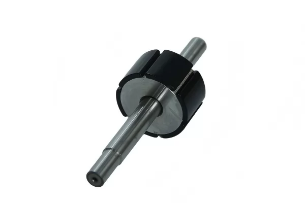
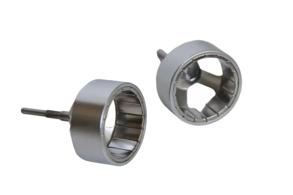
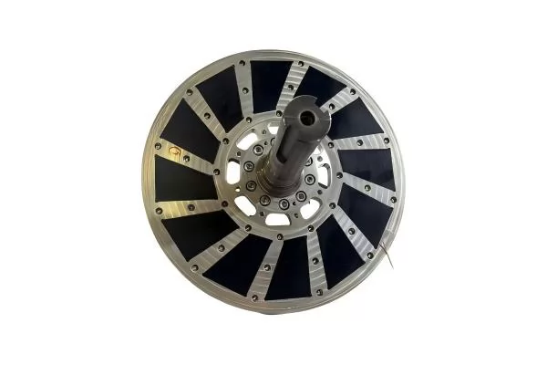
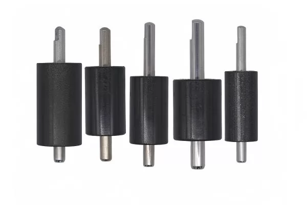
Rotor architectures require different control plans
Four design decisions that prevent expensive rework
Choose functional datums
Reference the shaft journals, bearing seats or pilot features that locate the rotor in the actual motor. Avoid building critical runout requirements from convenient but non-functional manufacturing surfaces.
Control the assembled envelope
Define the feature that must rotate within clearance: magnet OD, sleeve OD, rotor shell ID or axial magnet face. Component inspection alone cannot prove the final air gap.
Budget the tolerance stack
Allocate variation to the core, magnets, bondline, sleeve, hub and joining process. Use worst-case analysis for clearance risks and statistical analysis where stable production data supports it.
Match tolerances to inspection
Specify measurable characteristics and suitable gaging. CMM, roundness instruments, dial indicators, air gages and dedicated fixtures each have different strengths and uncertainty.
Common rotor controls and what they protect
| Control Item | Functional Effect | Typical Inspection | Engineering Note |
|---|---|---|---|
| Shaft journal runout | Bearing alignment and rotor orbit | Between centers, indicator or roundness instrument | Measure from the same datum relationship used in final motor assembly. |
| Rotor OD concentricity / runout | Radial air-gap uniformity and rub clearance | Datum fixture with indicator, CMM or roundness instrument | State whether the requirement applies before or after sleeve installation. |
| Magnet radial position | Air gap, flux symmetry and torque ripple | Profile fixture, CMM, vision system or functional gage | Include magnet thickness and adhesive bondline in the stack analysis. |
| Magnet angular position | Electrical angle, cogging and back-EMF symmetry | Vision, CMM or dedicated indexing fixture | Link mechanical clocking to polarity and magnetization records. |
| Sleeve concentricity | Clearance, stress distribution and balance | Indicator or roundness measurement after assembly | Press fit, winding tension and cure conditions can change final geometry. |
| Axial face runout | Axial-flux air gap and thrust behavior | Surface plate / indicator, CMM or rotary fixture | Inspect the functional magnet face relative to the mounting datum. |
| Dynamic unbalance | Vibration, bearing load and acoustic noise | Dynamic balancing machine at defined planes | Balance does not replace runout inspection; a geometrically eccentric rotor can still be balanced. |
Important: Numerical tolerances are application-specific. Rotor diameter, speed, bearing arrangement, thermal growth, assembly method and required air gap must be reviewed before limits are released on the drawing.
Where the tolerance chain changes
Inner rotor motors
The shaft axis is usually the primary radial reference. Control core-to-shaft location, magnet or sleeve OD runout, axial stack position and balance correction features.
Outer rotor motors
The shell, hub and bearing connection establish the rotating axis. Magnet ID variation and shell distortion can reduce the available internal air gap.
Axial-flux motors
Flatness, parallelism and face runout dominate. Magnet height, adhesive thickness and carrier deformation must be evaluated at operating temperature.
Bonded magnet rotors
Material flow, molding shrinkage, insert position and post-machining determine the final magnetic and mechanical axis. Tooling datums should support later inspection.
From tolerance analysis to repeatable rotor production
Information needed for a rotor assembly review
Motor rotor tolerance questions
Is concentricity the same as runout?
No. Concentricity describes the relationship of derived centers or axes, while runout evaluates surface variation during rotation about a datum axis. The correct control depends on the functional requirement and the planned measurement method.
Why can a balanced rotor still have an air-gap problem?
Balancing corrects mass distribution. It does not necessarily correct geometric eccentricity, sleeve runout or an incorrectly positioned magnet surface. Geometry and mass properties must be validated separately.
Should the rotor be inspected before or after magnet bonding?
Both stages can be useful. Pre-assembly inspection confirms incoming parts, while post-bonding inspection captures bondline, fixture, cure and assembly effects. The final functional surface should always be verified at the stage stated on the drawing.
Can Ningbo Vanguard support prototype and production rotor assemblies?
Yes. Ningbo Vanguard Technologies Co., Ltd supports magnet selection, tolerance review, rotor prototyping, assembly process development, inspection planning and production-oriented motor component supply.
Engineering Support
Turn a tight air-gap target into a measurable production plan
Send your rotor drawing, speed range, operating temperature and inspection requirements. Our engineering team can review the tolerance chain and propose a prototype-to-production control plan.


