
Electric Motor Thermal Engineering
Motor Insulation Class, Temperature Rise and Winding Life
A practical guide to thermal class, ambient temperature, winding rise, hot-spot margin, PWM electrical stress and insulation-system validation.
Insulation class is a system capability, not an ambient-temperature rating
A motor winding is built from magnet wire enamel, slot liner, phase insulation, wedges, impregnation resin, lead insulation, tapes and connection materials. These components work together as an electrical insulation system. Its thermal class indicates an evaluated temperature capability under defined ageing criteria; it does not mean that every motor carrying that class can operate continuously in an ambient equal to the class temperature.
Actual winding temperature is created by ambient or coolant temperature plus motor temperature rise, with additional allowance for the difference between measured average winding temperature and the hottest local point. Mechanical components, bearings, magnets, sensors and adhesives may impose lower limits than the winding insulation.
Represents the evaluated insulation system, not one material in isolation.
Increase above the reference cooling medium under a defined load and method.
The hottest conductor region can exceed the measured winding average.
Thermal ageing accumulates across the complete duty cycle.
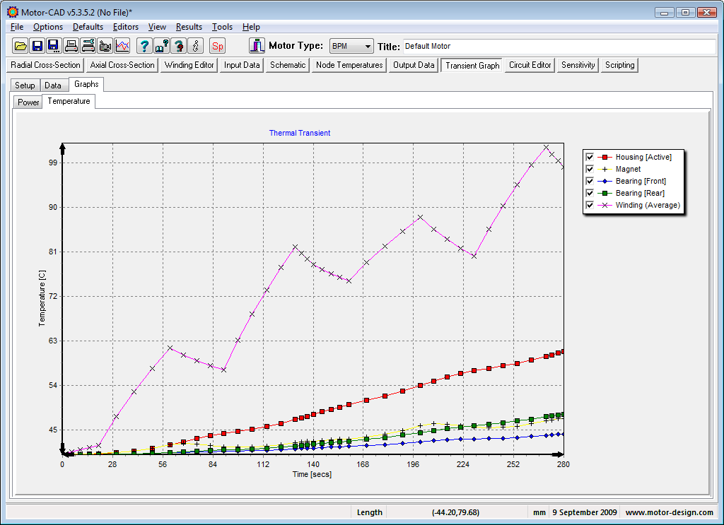
Winding construction, insulation placement and thermal analysis


Common insulation-system class designations
| Thermal Class | Class Temperature | Common Motor Context | Important Limitation |
|---|---|---|---|
| Class A | 105°C | Legacy or lightly loaded insulation systems | Lower thermal reserve than modern B, F or H systems |
| Class E | 120°C | Compact appliances and selected low-voltage windings | Less commonly specified in some industrial motor markets |
| Class B | 130°C | General industrial motors and established winding systems | Motor temperature-rise limit depends on the applicable standard and test method |
| Class F | 155°C | Widely used industrial and inverter-duty motor insulation systems | Class F materials do not automatically permit Class F rise in every design |
| Class H | 180°C | High-temperature or high-power-density motor designs | Bearings, magnets, adhesives and sensors may have lower temperature limits |
| Class 200 and above | 200°C, 220°C or higher class designations | Specialized aerospace, downhole and severe-temperature equipment | Requires a qualified complete insulation system and application-specific validation |
Standards note: IEC 60085 distinguishes thermal classification of insulating materials from that of complete electrical insulation systems. Motor winding temperature-rise limits are defined separately by the applicable machine standard, rating, construction and measurement method.
Temperature Budget
Build the limit from several temperature components
- Ambient or coolant: the actual cooling-medium temperature entering the thermal system.
- Motor temperature rise: heat produced by copper, iron, mechanical and stray losses.
- Hot-spot allowance: difference between the measured or calculated average and the local maximum.
- Measurement uncertainty: sensor location, resistance method and transient timing affect the result.
- Design margin: reserve for production variation, fouling, voltage variation and ageing.
- Other component limits: bearings, grease, magnets, encoders, adhesives and seals may govern.
Illustrative thermal budget
Ambient / coolantMeasured riseHot-spot allowanceDesign margin
Reference only
The proportions are conceptual. Use the applicable standard, duty cycle and measured component temperatures for a real motor.
What the nameplate insulation class does not tell you
Not the ambient limit
Class F does not mean the motor can run in 155°C ambient. Ambient, rise, hot spot and margin share the budget.
Not a single material
High-temperature wire enamel cannot compensate for an unqualified liner, resin, lead wire or phase barrier.
Not the rise rating
A motor can use Class F insulation while being designed for a lower Class B temperature rise.
Not a guaranteed life
Thermal class is based on evaluated endurance criteria; real life also depends on electrical, mechanical and environmental stress.
Where winding temperature rise comes from
| Heat Source | Primary Driver | Operating Sensitivity | Design Response |
|---|---|---|---|
| Copper loss | Phase current, conductor resistance and AC effects | Usually increases strongly with current; resistance rises as copper heats | Conductor area, fill factor, winding layout, current density and cooling path |
| Core loss | Flux density, electrical frequency, harmonics and lamination material | Important at high speed, high frequency and PWM excitation | Silicon steel grade, lamination thickness, flux density and control strategy |
| Rotor loss | Slip, harmonic fields, magnet eddy currents and conductive sleeves | Can heat magnets, cage, sleeve and bearings away from winding sensors | Segmentation, material conductivity, harmonic control and cooling |
| Mechanical loss | Bearings, seals, windage and fluid drag | Often increases rapidly with speed | Bearing selection, lubrication, air-path design and rotor surface geometry |
| Contact and connection loss | Terminal, weld, crimp or busbar resistance | Localized hot spots may not appear in average phase resistance | Joint design, process monitoring and end-of-line resistance checks |
| Stray load loss | Leakage flux, circulating current and construction details | Depends on load and local metallic paths | FEA, prototype correlation and local temperature instrumentation |
Inverter-fed windings face more than thermal ageing
High dv/dt raises inter-turn and phase-to-ground electrical stress, especially near the line end.
Long motor cables and impedance mismatch can increase terminal voltage overshoot.
Void, spacing and voltage conditions can initiate discharge in insulation systems not designed for the stress.
Current and voltage harmonics can raise copper, core and rotor losses beyond sinusoidal operation.
High-frequency coupling affects winding-to-frame stress and can contribute to bearing-current problems.
Electrical pulses combine with heat, vibration, moisture and contamination over the motor lifetime.
Average load can hide a damaging transient hot spot
| Operating Pattern | Thermal Behavior | Main Risk | Required Analysis |
|---|---|---|---|
| Continuous rated load | Approaches thermal equilibrium when cooling remains stable | Underestimated steady losses or cooling resistance | Steady-state thermal model and stabilized temperature-rise test |
| Repeated peak torque | Copper heats rapidly while housing temperature responds more slowly | Conductor hot spot exceeds limit even when case temperature appears safe | Transient winding model using current-time profile |
| Low-speed high torque | High copper loss with reduced shaft-mounted fan airflow | Insufficient cooling at the most demanding current point | Speed-dependent cooling and inverter-duty test points |
| Frequent start-stop | Repeated current peaks and thermal cycling | Thermal fatigue at joints, end turns and dissimilar materials | Cycle accumulation, peak temperature and expansion review |
| Short high-speed burst | Core, rotor and windage losses rise while duration may limit heat soak | Localized rotor or end-region hot spots | Transient multi-node or FEA model with speed-dependent losses |
| Regeneration | Current and losses can remain significant during negative torque | Thermal model based only on motoring quadrant misses the event | Full four-quadrant operating map |
External conditions change available thermal margin
High ambient
Reduces the temperature rise available before components reach their limits.
High altitude
Lower air density can reduce convective cooling and may require derating or redesign.
Blocked airflow
Dust, guards, packaging and installation clearances can change the tested cooling path.
Coolant variation
Flow, inlet temperature, mixture, pressure drop and fouling affect liquid-cooled performance.
Materials must remain compatible through manufacturing and service
| System Element | Primary Function | Manufacturing Stress | Service Risk |
|---|---|---|---|
| Magnet wire enamel | Turn-to-turn electrical insulation | Winding tension, tooling contact, bending and insertion abrasion | Thermal ageing, surge voltage and partial discharge |
| Slot liner | Separates winding from lamination stack | Edge damage, burr contact, folding and insertion movement | Ground-wall breakdown, vibration wear and moisture |
| Phase insulation | Separates phase groups and connections | Placement error, compression and insufficient overlap | Phase-to-phase surge and thermal movement |
| Impregnation resin | Supports conductors, fills voids and improves heat transfer | Viscosity, penetration, cure, drainage and void formation | Cracking, chemical attack, thermal ageing and poor heat transfer |
| Lead and connection insulation | Protects flexible leads, welds and terminations | Routing, stripping, welding heat and strain | Movement, rubbing, terminal heating and contamination |
| Slot wedge and lacing | Retains winding and controls movement | Insertion force, fit and end-turn tying | Looseness, vibration, abrasion and thermal expansion |
From operating map to qualified insulation system
Use multiple methods because each one sees a different temperature
| Method | What It Represents | Strength | Limitation |
|---|---|---|---|
| Winding resistance | Average conductor temperature inferred from resistance change | Directly related to copper and practical for standardized rise testing | Does not locate the hottest turn and requires controlled timing after shutdown |
| Embedded RTD | Local temperature near the sensor position | Continuous monitoring and useful protection input | Sensor may miss the true hot spot or alter local construction |
| Thermocouple | Local contact temperature at an accessible point | Fast, compact and suitable for prototype mapping | Attachment, lead routing and electrical noise affect accuracy |
| Infrared imaging | Visible surface temperature distribution | Quickly reveals end-turn, terminal and cooling nonuniformity | Cannot see buried slot conductors; emissivity and line of sight matter |
| Fiber-optic sensor | Local temperature in high-voltage or high-EMI areas | Electrical isolation and good transient response | Cost, installation fragility and limited sensing locations |
| Thermal model | Estimated internal node temperatures across the duty cycle | Predicts inaccessible hot spots and design alternatives | Requires calibrated losses, contact resistances and cooling boundaries |
Evidence needed before releasing the winding design
Confirm enamel, liner, resin, leads and cleaners remain compatible after cure and ageing.
Control liner placement, winding damage, impregnation penetration, resin mix and cure profile.
Compare measured average and local temperatures with the model at critical duty points.
Use appropriate resistance, hipot, surge and partial-discharge testing for the voltage system.
Combine heat with humidity, fluids, vibration or thermal cycling relevant to the application.
Define end-of-line limits, trend data, sampling audits and reaction plans for insulation defects.
Early evidence of insulation-system distress
Phase resistance drift
Imbalance can indicate connection heating, conductor damage or measurement-temperature inconsistency.
Insulation resistance decline
Moisture, contamination or thermal degradation can reduce resistance to ground.
Surge waveform mismatch
Turn-to-turn weakness may appear before a full phase-to-ground breakdown.
Localized discoloration
Darkened resin, leads or end turns can reveal persistent thermal concentration.
Information needed for a winding thermal review
Motor insulation and temperature questions
Does Class F insulation mean a motor can operate at 155°C ambient?
No. The class temperature applies to the evaluated insulation system. The motor temperature budget also includes ambient or coolant temperature, winding rise, hot-spot allowance and design margin.
What does Class F insulation with Class B rise mean?
It generally means the motor uses a Class F insulation system but is designed so the rated-load temperature rise stays within a lower Class B rise limit under the stated conditions, providing thermal reserve.
Is average winding temperature enough?
No. Average temperature from resistance testing is valuable, but local slot, end-turn, connection or terminal hot spots can be higher and should be addressed through sensors, modelling or targeted testing.
Why can an inverter-fed motor run hotter?
PWM harmonics can add copper, core and rotor losses, while low-speed operation may reduce self-ventilation. Fast voltage edges also create additional electrical stress on the insulation system.
Can changing the impregnation resin affect motor life?
Yes. Resin influences thermal transfer, mechanical support, void content, chemical compatibility and electrical endurance. A material substitution should be reviewed as a change to the insulation system and process.
Motor Thermal Engineering
Request a Winding Thermal ReviewTurn insulation class into a verified temperature and lifetime margin
Send your winding design, operating map, cooling conditions and insulation materials for thermal analysis, DFM and prototype validation planning.


