Product Overview
Injection Molded Ferrite Magnets
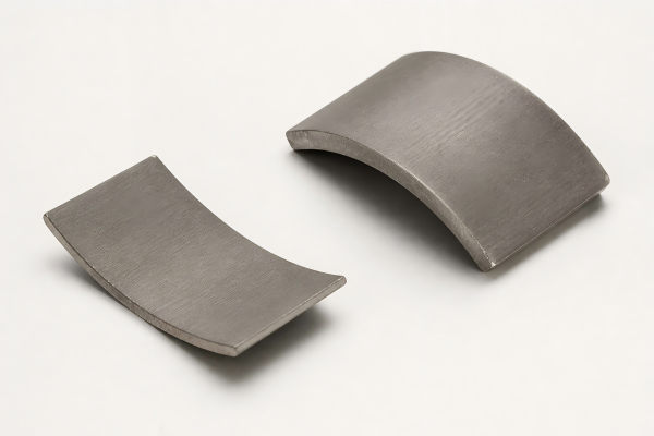
Injection molded ferrite magnets are bonded ceramic magnets produced by compounding ferrite magnetic powder with thermoplastic resin, then injecting the compound into precision molds. This process combines the corrosion resistance and cost advantage of ferrite with the design flexibility of plastic injection molding.
Unlike sintered ferrite magnets, injection molded ferrite magnets can be made into complex shapes, thin-wall rings, multi-pole rotors, sensor wheels, gears, carriers and insert-molded components with minimal secondary machining. They are suitable for high-volume products that require stable magnetic performance, integrated structure and competitive unit cost.
Ningbo Vanguard Technologies supplies custom injection molded ferrite magnets in different resin systems, magnetic grades, dimensions and magnetization patterns. Our team supports material selection, mold development, insert design, prototype sampling, multi-pole magnetization and mass production quality control.
Products can be supplied as molded magnets, overmolded magnetic parts, insert-molded rotors, sensor rings, magnetic wheels or complete magnetic assemblies. Typical sample lead time is 10–15 working days after drawing and tooling review.
Quick View
Injection Molded Ferrite Magnet Selection Snapshot
Ferrite + Resin
Injection Molded Material
Ferrite magnetic powder compounded with thermoplastic resin for economical molded magnetic components.
Complex Shape
High Design Freedom
Suitable for sensor rings, magnetic wheels, gears, hubs, carriers and insert-molded parts.
Multi-Pole
Flexible Magnetization
Stable pole distribution for speed sensors, encoder wheels, small motors and automotive modules.
10-15 Days
Prototype Sample Lead Time
Fast sampling after drawing, resin system, grade and magnetization fixture are confirmed.
Material Selection Guide
PPS Binder
Heat resistance
Insert Molded
Integration
Application Demand Focus
Small Motors
Cost control
Sensor Rings
Pole accuracy
Magnetic Wheels
Integration
1Drawing ReviewShape, insert, tolerance, assembly fit
2Material MatchFerrite powder, resin, loading ratio
3Mold PlanTooling, gate, insert, shrinkage
4MagnetizationAxial, radial, multi-pole fixture
5InspectionFlux, size, polarity, appearance
Key Applications
Small Motors
Used in low-power DC motors, fan motors, pump motors and appliance motors where molded rotors reduce assembly steps and support stable high-volume production.
Sensor Rings
Suitable for speed sensors, position sensors, Hall sensors and rotary detection systems requiring molded reference features and consistent pole distribution.
Automotive Components
Applied in sensor wheels, low-power actuators, HVAC components, fluid meters and automotive modules where ferrite provides stable and economical performance.
Magnetic Wheels
Used for magnetic encoder wheels, timing wheels, pulse wheels and rotating detection parts requiring integrated teeth, hubs or shaft features.
Office Automation
Used in printers, scanners, copiers, paper-feed systems and toner mechanisms requiring molded magnetic parts with low unit cost.
Consumer Products
Suitable for toys, meters, appliance controls, smart devices and compact mechanisms that need corrosion-resistant molded magnetic components.
Grade & Magnetic Properties
Typical grades for injection molded ferrite magnets. Values are for reference at 20 °C; final performance depends on ferrite powder type, resin system, powder loading ratio, molding condition, part geometry and magnetization fixture.
Typical Physical Properties
|
Parameter |
Unit |
Typical Value |
|
Density |
g/cm3 |
3.0–4.2 depending on powder loading |
|
Binder System |
– |
PP / PA / PPS / custom engineering plastic |
|
Electrical Resistivity |
Ω·cm |
High, suitable for low eddy-current loss |
|
Working Temperature |
°C |
Typically 100–150 °C, resin dependent |
|
Corrosion Resistance |
– |
Excellent due to ferrite powder and polymer binder |
|
Process Advantage |
– |
Complex shape, insert molding, multi-pole magnetization and low unit cost |
Magnetization Orientations Available
Diametrical Magnetization
Dimension Capability
Injection molding is suitable for ferrite rings, discs, wheels, gears, carriers, thin-wall rotors and components with positioning features. Mold design should consider flow path, demolding direction, shrinkage, insert retention and magnetization fixture access.
|
Item |
Capability |
Notes |
|
Outer Diameter / Length |
3–180 mm typical |
Larger sizes reviewed by mold and injection capacity |
|
Wall Thickness |
Thin-wall and complex parts available |
Confirmed by flow, strength and powder loading |
|
Standard Tolerance |
±0.05 mm to ±0.15 mm |
Depends on resin, size, mold and critical dimensions |
|
Integrated Features |
Gear, hub, shaft insert, slot, keyway, marker, carrier |
Designed for assembly and magnetization inspection |
Design Support
How to Specify Injection Molded Ferrite Magnets
Material System
Choose resin and ferrite powder loading based on magnetic output, working temperature, mechanical strength, humidity exposure and cost target.
Mold & Insert Design
Confirm insert position, flow direction, gate location, shrinkage, critical dimensions and demolding direction before tooling.
Magnetization Pattern
Define pole count, pole width, phase angle, reference mark, polarity direction and inspection method for multi-pole rings and sensor wheels.
Custom Manufacturing
Available Custom Features
Ring, disc, wheel, gear, rotor, sensor wheel, overmolded insert, thin-wall part and custom 3D profile.
Encoder, pulse wheel, motor rotor, sensor ring, actuator, pump rotor and magnetic module.
PP, PA, PPS, custom engineering plastic, color marking, polarity marking and protective packaging.
Temperature resistance, humidity protection, visual identification and assembly compatibility.
Shaft insert, metal hub, plastic carrier, bonding, balancing, polarity marking and packed-by-pole direction.
Reducing customer assembly steps and improving consistency of magnetic sub-assemblies.
Production Control
Manufacturing & Quality Assurance
The production process includes ferrite powder preparation, thermoplastic compounding, pelletizing, injection molding, insert molding if required, finishing, magnetization and final inspection. Key controls include powder loading, melt flow, mold temperature, shrinkage, insert retention, magnetization fixture and batch traceability.
Magnetic Inspection
Surface flux, pull force, pole count, pole angle, phase position, polarity direction and batch consistency can be inspected according to project requirements.
Dimensional Inspection
OD, ID, thickness, concentricity, runout, insert position, gear profile, flatness and critical assembly dimensions are checked before shipment.
Documentation
Material certificate, magnetic report, dimensional report, RoHS/REACH documents and project-specific quality files are available on request.
Fast Quotation
Information Needed for Fast Quotation
For faster engineering review, please provide drawing or 3D file, target grade or surface flux, critical dimensions and tolerance, resin requirement, magnetization direction, pole count or polarity requirement, working temperature, insert or assembly requirement, sample quantity and annual volume. If the material is not fixed, our team can recommend an injection molded ferrite solution based on magnetic output, geometry and cost target.
Frequently Asked Questions
What is the difference between injection molded ferrite and sintered ferrite?
Sintered ferrite usually has higher magnetic output, while injection molded ferrite offers complex shape capability, insert molding, multi-pole patterns and lower assembly cost for high-volume parts.
Can injection molded ferrite magnets be multi-pole magnetized?
Yes. Multi-pole magnetization is widely used for sensor wheels, pulse wheels and small motor rotors. Pole count, phase angle and inspection method should be defined before fixture development.
Can shafts or plastic carriers be molded together with the magnet?
Yes. Insert molding is a common solution. Shafts, hubs, bushings, gears and plastic carriers can be integrated depending on product structure and tooling feasibility.
Do injection molded ferrite magnets require coating?
Usually no coating is required because ferrite and polymer binder both have good corrosion resistance. Special surface treatment can be discussed for marking, wear protection or bonding needs.
What is the lead time for custom injection molded ferrite magnets?
Prototype timing depends on tooling and material selection. Typical sample preparation is 10–15 working days after tooling and drawing confirmation; mass production depends on mold complexity, quantity and inspection requirements.