Hairpin Winding
Contact Us Now
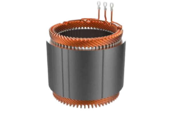
Hairpin winding is a rectangular copper conductor winding technology used in high-power-density motors and generators. Instead of using flexible round wire coils, pre-formed copper bars are inserted into stator slots, twisted, connected and welded to create a compact winding structure with high slot fill, low DC resistance and excellent repeatability.
This winding method is widely used in EV traction motors, hybrid vehicle motors, high-efficiency PMSM motors, generators, compressors and compact industrial drives. Hairpin winding helps improve copper utilization, thermal conduction and automated production consistency, especially when the motor design requires high current capability and stable batch quality.
Ningbo Vanguard Technologies supports custom hairpin winding development for motor stators and wound stator assemblies. We can assist with conductor size review, slot insulation, hairpin forming, insertion, twisting, welding, end-turn shaping, varnish or potting, lead connection and electrical inspection.
Whether you need prototype hairpin wound stators for motor development or production-ready assemblies, Vanguard can review slot geometry, conductor dimensions, layer count, parallel path, phase connection, insulation class, cooling structure and test requirements to provide a practical manufacturing plan.
Hairpin winding structures are selected according to slot geometry, conductor size, layer number, cooling method, current density and motor performance target.
| Winding Type | Structure | Main Advantage | Typical Application | Engineering Notes |
|---|---|---|---|---|
| 2-Layer Hairpin | Two conductor layers in each slot | Simpler process and lower tooling complexity | Prototype motors, lower power designs | Useful for early validation and simpler connection layouts. |
| 4-Layer Hairpin | Four conductor layers with twisted ends | Balanced manufacturability and performance | EV motors, PMSM, industrial drives | Common structure for compact high-efficiency motors. |
| 6/8-Layer Hairpin | Multiple conductor layers per slot | Higher current capacity and flexible parallel paths | High-power traction motors | Requires precise forming, insertion and welding process control. |
| Wave Hairpin Winding | Continuous or wave-style conductor path | Reduced connection count in selected designs | Advanced high-volume motors | Manufacturing feasibility should be reviewed with tooling plan. |
| Flat Wire Distributed Hairpin | Rectangular wire distributed across slots | Improved slot fill and waveform control | PMSM, generators, traction systems | Slot insulation and AC loss should be evaluated. |
| Oil-Cooled Hairpin Stator | Hairpin stator matched with oil cooling path | Improved thermal performance | EV traction and high-load drives | End-turn shape, insulation and oil compatibility are critical. |
The final hairpin winding specification is confirmed according to motor power, slot geometry, conductor size, phase layout, insulation class, cooling method and production requirement.
| Item | Available Options | Engineering Notes |
|---|---|---|
| Stator Structure | Inner stator, outer stator, EV stator, generator stator, custom laminated core | Slot opening, stack height and tooth geometry determine conductor insertion feasibility. |
| Conductor Type | Rectangular copper wire, enamelled flat wire, formed copper bar, custom copper profile | Conductor width, thickness and corner radius should match slot and insulation design. |
| Layer & Path | 2-layer, 4-layer, 6-layer, 8-layer, parallel paths, series paths | Layer count affects current capacity, connection complexity and end-turn geometry. |
| Connection Method | Laser welding, TIG welding, resistance welding, brazing support, terminal connection | Joint strength, resistance and heat-affected area should be controlled and inspected. |
| Insulation System | Slot liner, conductor enamel, phase paper, sleeve, wedge, varnish, resin potting | Insulation class and partial discharge risk should be reviewed for high-voltage motors. |
| Cooling Compatibility | Air cooling, water jacket, oil spray, oil immersion, thermal potting | Thermal path, oil compatibility and end-turn clearance must be considered. |
| Inspection | Resistance, weld section check, hipot, insulation resistance, surge test, phase sequence | Test items are selected according to motor voltage, power level and customer standard. |
| Factor | Risk If Ignored | Recommended Control |
|---|---|---|
| Forming Accuracy | Poor insertion, insulation damage or uneven end-turn height | Use controlled forming fixtures and verify conductor geometry before insertion. |
| Slot Insulation | Short circuit, partial discharge risk or hipot failure | Define slot liner, phase paper, wedge and insulation class according to voltage level. |
| Twist Alignment | Welding mismatch, high joint resistance or mechanical stress | Control twist angle, cut length and joint position with dedicated fixtures. |
| Welding Process | Weak joint, spatter, overheating or inconsistent resistance | Validate welding parameter, joint strength, resistance and visual quality. |
| End-Turn Clearance | Interference with housing, cooling path or rotor assembly | Define maximum end-turn envelope and verify clearance during prototype build. |
| Electrical Testing | Hidden insulation or connection defects | Perform resistance, hipot, insulation resistance, surge and phase sequence tests as required. |