Profile DFM
Review wall transitions, radii, hollow chambers, fins and die support. Identify difficult features before tool design.

Ningbo Vanguard Technologies Co., Ltd
Custom aluminum profiles, developed from cross-section design to assembly-ready components.
Vanguard coordinates profile review, alloy and temper selection, die development, extrusion, CNC machining, surface finishing and inspection for motor housings, thermal components and industrial structures.
Start with the final assembly: section geometry, functional datums, finished length and production volume determine the practical manufacturing route.

Profile to Part
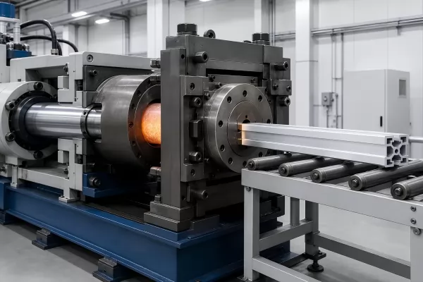
Extrusion forms a continuous cross-section by pushing heated aluminum through a shaped die. It can reduce material removal for repeated sections, while cutting and CNC machining add features that vary along the length.
For a motor housing, an extruded bore may provide stock for final machining. Bearing seats, stator fits and sealing faces need a datum scheme and machining allowance that account for profile variation and distortion.
Service Scope
Define the complete supply scope before committing to die tooling.
Review wall transitions, radii, hollow chambers, fins and die support. Identify difficult features before tool design.
Plan solid or hollow tooling around the alloy, section and order volume. Use trial sections to agree corrections and approval.
Coordinate extrusion, cooling, straightening and heat treatment as required by the selected alloy and temper.
Cut to length, face, bore, mill, drill and tap around the final drawing and functional datums.
Specify mill finish, anodizing, brushing or powder coating, with masking and appearance samples where needed.
Check profile dimensions, straightness, twist, machined features and finish, then protect critical surfaces for transport.
Project Workflow
Sample approval should cover the finished component, including machining and coating.
Confirm section drawing, finished length, loads, mating parts, finish, quantity and schedule.
Review section feasibility, die route, alloy, temper and machining allowance.
Inspect sample sections for geometry, surface quality and stable flow; correct tooling as required.
Apply the intended cutting, machining and finishing sequence to representative samples.
Verify critical features, functional fit and appearance against agreed acceptance criteria.
Control batches, die condition, heat treatment, machining, inspection and packaging.
Material Selection
Strength and thermal properties depend on alloy, temper and product condition. Final values must come from the agreed material specification.
| Alloy | Selection Considerations | Typical Part Direction | Review Before Release |
|---|---|---|---|
| 6063 | Complex profiles, cosmetic surfaces and useful extrudability | Finned heat sinks, enclosures and hollow sections | Confirm temper, fin geometry, structural load and finish requirements. |
| 6061 | Strength, machinability and general structural use | Machined housings, mounting profiles and structural parts | Complex thin features can be harder to extrude; review die feasibility. |
| 6005 / 6005A | Structural profile applications | Rails, supports and framework | Specify the exact alloy designation and temper; these are not interchangeable labels. |
| 6082 | Structural strength where section geometry permits | Loaded supports and machined structural profiles | Review extrusion complexity, quench response and dimensional control. |
Design Review
Resolve these points before approving the section and die.
Use balanced wall thickness and gradual transitions. Deep narrow channels, thin fins and sharp corners need a die feasibility review.
Specify limits over the actual finished length. Long profiles can bend or twist during processing and handling; define measurement supports.
Mark bearing bores, stator fits, sealing faces and mounting datums. Allow enough stock to clean up expected profile variation.
Identify visible faces, electrical contact areas and masked fits. Coating thickness and surface preparation affect dimensions and assembly.
Motor & Industrial Applications
Choose extrusion where a repeated section and production demand justify the die.
Tubular sections with fins, ribs or mounting features, followed by machining of critical fits and end interfaces.
Finned sections for power electronics and drives. Fin spacing, airflow and thermal interfaces need application-specific review.
Hollow profiles with cover grooves and mounting channels, cut and machined for connectors and fasteners.
T-slots, guides and support sections for frames and automation equipment, sized for stiffness and connection loads.
U-sections, C-sections and asymmetric profiles for tracks, guards and equipment supports.
Finished profiles combined with covers, inserts, fasteners or other components according to the assembly drawing.
Quality Planning
Agree on inspection criteria for both the extrusion and its downstream operations.
| Control Area | Potential Risk | Verification |
|---|---|---|
| Alloy & Temper | Insufficient strength or inconsistent machining behavior | Approved alloy and temper; material certificates and agreed property checks. |
| Cross-Section | Wall variation, profile mismatch or die wear | Section measurements, functional gauges and die correction records. |
| Straightness & Twist | Poor assembly fit over the finished length | Defined inspection length, support condition and measurement method. |
| Machined Interfaces | Misaligned bearing seats, threads or sealing faces | Datum-based inspection, bore checks and thread gauges. |
| Surface Treatment | Coating buildup, color variation or electrical isolation | Finish samples, thickness checks and masking instructions. |
| Handling & Traceability | Scratches, dents or mixed material batches | Protected contact surfaces, batch identification and packing requirements. |
Profile Examples
Representative images illustrate profile shapes and processing; third-party facilities shown are reference examples.

RFQ Preparation
A section sketch alone rarely defines the cost of a finished component.
2D section, 3D model, revision, alloy, temper, finished lengths and mechanical requirements.
Datums, bores, threads, straightness, twist, mating parts and machining requirements.
Coating type, visible faces, masking, color standard, inspection and packaging requirements.
Sample quantity, batch sizes, annual demand, tooling expectations and delivery milestones.
Engineering Questions
Send the section and finished-part drawing for a review of tooling, machining and inspection requirements.
Contact Vanguard6063 is often considered for complex or appearance-sensitive profiles. 6061 is commonly reviewed where structural and machining requirements are important. Geometry, temper and specified properties determine the final choice.
A precision bearing seat usually needs machining. Specify its tolerance, datum relationship and surface finish, and retain sufficient stock on the profile.
No. Hollow-die construction, longitudinal seams, machining and end closures must be assessed. Define leak or pressure tests for fluid-carrying components.
Dedicated tooling and minimum production runs affect cost. Existing profiles or CNC-machined prototypes may be practical for early validation; compare the complete finished-part cost.
Yes. Anodizing changes surface dimensions and electrical behavior. Define coating thickness and masking requirements for precision fits, threads and contact areas.
Die complexity, trial corrections, alloy availability, heat treatment, machining and finishing all affect timing. The quotation should identify each approval milestone.
Send your section, alloy, finished-part drawing and annual demand for review.