Drilling
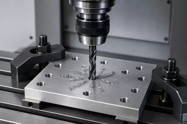
Through, blind and stepped holes with controlled diameter, depth and entry or exit edges.

Ningbo Vanguard Technologies Co., Ltd
Accurate hole locations, verified threads and assembly-ready fastening features.
Vanguard supports drilling, tapping, reaming, counterboring and countersinking for housings, motor components, brackets and fixtures. We coordinate material review, workholding, hole preparation, threading, deburring and inspection around your finished-part drawing.
Reliable assembly depends on more than nominal thread size. Datum location, usable thread depth, engagement, cleanliness and the final surface condition all need to be defined.
Drawing to Assembly
A clearance hole, locating bore and tapped hole have different acceptance requirements. We review the mating hardware, material, datum system and access before defining the process and inspection plan.
For blind tapped holes, the usable full thread ends before the drilled bottom. The drawing should distinguish full thread depth, full-diameter drill depth and any drill-point allowance, while leaving room for the selected tool and chip control.
Service Scope
Select the machining route from the feature, material and quantity.
Through, blind and stepped holes with controlled diameter, depth and entry or exit edges.
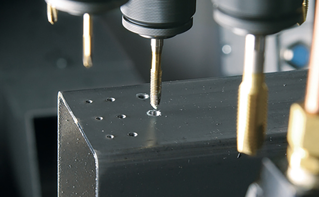
Review cutting taps, forming taps or thread milling according to material, hole access, pitch and batch requirements.
Finish locating and dowel holes to the specified fit. Plan the pre-hole and datum relationship before reaming.
Create screw seats and flush mounting features with controlled depth, diameter, angle and alignment.
Evaluate threaded inserts for repeated assembly or weaker base materials; machine the correct insert-specific hole and thread.
Remove chips and burrs, protect critical edges and inspect against the agreed hole and thread requirements.
Project Workflow
Keep the datum scheme and final acceptance condition consistent throughout the process.
Confirm material, hardness, hole callouts, thread standard, depth, coating and inspection requirements.
Choose workholding, tool access, cutting method, lubrication and a practical machining sequence.
Create pilot holes and seats with the allowance needed for reaming, tapping or thread milling.
Machine threads and precision features, then control chamfers, burrs and trapped chips.
Check size, depth, datum-related position and the specified thread gauge acceptance.
Complete the agreed finish, final inspection, cleanliness checks and protective packaging.
Feature Selection
Specify feature-level tolerances. A general machining accuracy does not define every hole on a part.
| Feature | Define on the Drawing | Inspection Approach | Engineering Consideration |
|---|---|---|---|
| Through Hole | Diameter, position, entry and exit chamfer | Pin gauges, bore measurement and datum-based checks | Control exit burrs and clearance behind the workpiece. |
| Blind Hole | Diameter, full-diameter depth and bottom form | Diameter and depth measurement | Distinguish cylindrical depth from drill-point depth. |
| Internal Thread | Standard, size, pitch, tolerance class and full thread depth | Specified thread gauges plus depth verification | Published M1-M30 scope is subject to material, geometry and tooling review. |
| Counterbore / Spotface | Diameter, depth and relationship to the main hole | Depth and diameter measurement | Check screw-head seating and remaining wall thickness. |
| Countersink | Included angle and diameter or defined depth | Suitable angle/size gauge or measurement | Match the actual fastener specification. |
| Reamed / Dowel Hole | Nominal size, fit, finish and datum-related position | Pin/bore gauges and coordinate measurement | H7 or H8 requires a nominal size to establish limits. |
DFM Priorities
Resolve access and acceptance requirements before releasing machining.
Size engagement from the screw load and base material. Allow for tool lead and clearance beyond the usable thread; avoid screw bottoming.
Reference functional locating surfaces. State the applicable position tolerance and any material-condition modifiers on the drawing.
Identify intersecting passages, exit edges and enclosed cavities that are difficult to clean. Protect sealing surfaces and precision bores.
Plating and anodizing can change fit. Define final acceptance after finishing, masking needs and whether any post-finish machining is permitted.
Material Review
Grade, hardness and condition matter as much as the material family.
Review adhesion, lubrication, chip removal and thread engagement. Inserts may be useful where repeated fastening or load requires them.
Confirm grade and hardness. Work hardening, cutting torque and tool wear influence the process plan.
Distinguish short-chipping brass grades from more ductile copper. Select appropriate tool geometry and chip control.
Review heat, access, tool life and tapping torque before committing to deep or small threaded features.
Consider heat, deformation, creep and insert retention. Inspect in the agreed material and environmental condition.
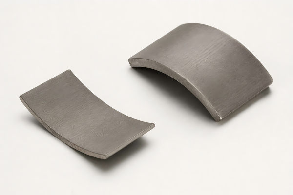
Define which carrier or housing is machined. Brittle permanent magnets require a separate machining review; control chips near magnets and bearings.
Inspection Planning
Thread fit, thread depth and hole position are separate checks.
| Control Area | Risk | Verification |
|---|---|---|
| Hole Size & Depth | Incorrect clearance, interference or bottoming | Calibrated pin/bore gauges and depth measurement matched to the tolerance. |
| Position & Perpendicularity | Assembly mismatch or misalignment | Datum-based CMM or suitable fixture measurement. |
| Thread Fit | Incorrect pitch diameter, form or class | GO/NO-GO gauging under the applicable thread standard. |
| Usable Thread Depth | Insufficient engagement despite a passing entrance | Depth verification using an appropriate gauge or measurement method. |
| Burrs & Cleanliness | Loose debris, damaged threads or contaminated assemblies | Agreed visual and cleanliness checks, including intersecting holes. |
| Finished Condition | Coating affects fit or exposes unprotected material | Final inspection after the agreed machining and finishing sequence. |
Process References
Reference images show machining operations; they do not establish Vanguard machine ownership or capacity.
RFQ Preparation
Include the finished-part drawing and the acceptance requirements.
Drawing revision, 3D model, grade, hardness, supplied condition and any existing coating.
Hole type, diameter, location, bottom form, thread standard, pitch, class and usable depth.
Critical datums, gauge requirements, inspection reports, cleanliness and surface treatment.
Sample and batch quantities, annual volume, supplied-part scope, packaging and delivery target.
Engineering Questions
Send the drawing and explain the mating part, fastener and finished surface condition.
Contact VanguardMetric, UNC, UNF and pipe-thread requirements can be reviewed against the drawing. State the exact designation: BSP parallel, BSP taper and NPT are different thread systems.
Specify usable full thread depth and drill depth separately, including the depth convention and bottom form. Tool lead, runout and chip clearance determine the additional space needed.
No. Forming taps displace suitable ductile material and require different pre-hole sizing. Use the tool supplier data for the material and thread requirement.
No. A thread gauge checks thread acceptance under its applicable standard. Location, orientation and usable depth need their own inspection method.
A mating screw can support a functional check but generally does not replace specified calibrated thread gauges for controlled acceptance.
M1-M30 threads can be reviewed. Feasibility, achievable tolerances and sample timing are confirmed against material, depth, geometry, quantity, tooling and inspection scope before order acceptance.
Send the drawing, material, thread details and quantity for an engineering review.