Casting DFM
Review wall transitions, ribs, bosses, draft, undercuts and parting lines against the component function.

Ningbo Vanguard Technologies Co., Ltd
Aluminum and zinc components, developed from casting design to verified assembly interfaces.
Vanguard supports custom die casting for motor housings, end covers, brackets, gearboxes and industrial enclosures. The project scope can include DFM, die development, casting, trimming, CNC machining, surface finishing and inspection.
We review the finished component before tooling: load paths, sealing faces, bearing fits, porosity limits and production volume define the manufacturing plan.

Casting to Component
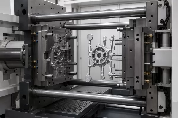
High-pressure die casting injects molten alloy into a reusable steel die. It can integrate walls, ribs, bosses and mounting features into a repeatable near-net-shape component when production demand justifies tooling.
Precision bearing seats, datums and sealing faces commonly require machining. Gate placement, solidification and machining stock need to be considered together because cutting can expose internal porosity.
Service Scope
Define the complete manufacturing route and the evidence needed to approve it.
Review wall transitions, ribs, bosses, draft, undercuts and parting lines against the component function.
Plan cavity layout, slides, gates, overflows, vents, cooling and ejection; evaluate samples before release.
Select an alloy-compatible process and review filling, thermal balance and venting. Vacuum assistance can be evaluated where required.
Remove gates and flash, deburr, then machine bores, faces, mounting holes and threads to the finished drawing.
Review blasting, coating, painting or plating against appearance, corrosion and assembly needs. Validate finish compatibility with the alloy.
Agree dimensional, internal-quality and functional checks, followed by assembly and protected packaging where specified.
Project Workflow
Each stage closes a specific casting, machining or assembly risk.
Confirm alloy, drawings, critical features, loading, finish, volume and validation criteria.
Review filling and solidification risks, parting lines, cores, ejection and machining datums.
Build the die, run initial trials and inspect filling, release, dimensions and representative internal quality.
Apply the intended machining and surface treatment to assess final fit, appearance and sealing.
Verify agreed dimensions, porosity zones, leak performance or structural requirements as applicable.
Control alloy batches, process settings, die maintenance, machining, inspection and change approval.
Material Review
Specify an exact grade and applicable material specification. Alloy names alone do not define finished-part performance.
| Material | Typical Considerations | Application Direction | Confirm During Review |
|---|---|---|---|
| ADC12 | Al-Si-Cu alloy commonly considered for complex general-purpose castings | Housings, covers and brackets | Confirm composition, porosity requirements and finish suitability. |
| A380 | Al-Si-Cu alloy widely used for general die-cast components | Industrial enclosures and mechanical components | Specify A380 explicitly; do not assume direct equivalence to ADC12. |
| Other Al-Si Grades | Application-specific balance of castability, thermal behavior and mechanical properties | Thermal or more demanding structural components | Select an identified grade; qualify process and any required heat treatment. |
| Zamak Grades | Fine detail and finish options, with greater density than aluminum | Small housings, hardware and compact brackets | Confirm exact grade, operating temperature, creep, weight and coating requirements. |
Thermal conductivity, strength and corrosion behavior vary by alloy and condition. A heat sink should be sized using verified properties and the actual thermal interface and airflow.
Design Review
Resolve these details before committing to the die and machining fixtures.
Use gradual transitions and appropriate ribs. Heavy junctions can create hot spots, shrinkage and uneven cooling.
Plan release direction, draft, slides and ejector contact locations. Identify visible and critical surfaces early.
Provide controlled stock for bearing seats and sealing faces. Review how machining depth interacts with internal-quality requirements.
Review air entrapment and solidification near stressed or sealing regions. Specify acceptable defect size, distribution and inspection zones.
Applications
Design the casting, mating parts and verification plan as one assembly.
Integrate ribs, mounting bosses and cable features, then machine bearing and stator interfaces as required.
Coordinate bearing supports, shaft alignment, oil passages and machined sealing faces.
Combine enclosure walls, screw bosses and heat paths, with controlled finish and gasket surfaces.
Use integrated fins and bases where geometry supports casting; verify conductivity and thermal performance.
Connect load paths with ribs and bosses while reviewing stress concentrations and local casting quality.
Define pressure, fluid, temperature and permitted leakage, then validate the finished machined component.
Quality Planning
Acceptance requirements should distinguish cosmetic, dimensional, internal and functional quality.
| Control Area | Risk to Address | Agreed Evidence |
|---|---|---|
| Alloy & Melt | Incorrect chemistry or inconsistent material quality | Grade verification and batch traceability; process records where required. |
| Filling & Die Condition | Cold shuts, incomplete fill, flash and die wear | Visual criteria, process monitoring and die-maintenance records. |
| Internal Quality | Gas pores, shrinkage or defects near critical features | Defined zones and acceptance limits; X-ray, CT or sectioning where specified. |
| Machined Dimensions | Bearing misalignment, poor fits or sealing-face error | Datum-based dimensional reports, bore checks and thread gauges. |
| Leak Performance | Connected pores or defective sealing interfaces | Test pressure, medium, temperature, stabilization time and leak-rate limit. |
| Surface & Packaging | Coating defects, finish mismatch or handling damage | Approved appearance samples, coating checks and protective packaging. |
Component Examples
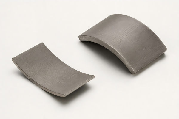
Third-party component photographs illustrate geometry and are not verified Vanguard production parts.

Quotation Inputs
Include the finished-part requirements along with the nominal casting geometry.
STEP model, dimensioned drawing, revision, specified grade and mechanical or thermal requirements.
Datums, bearing seats, threads, sealing faces, machining allowance and tolerance requirements.
Visible surfaces, coating, masking, porosity criteria, leak test and inspection documentation.
Sample quantity, batch size, annual demand, tooling expectations, packaging and delivery milestones.
Engineering Questions
Send the part drawing and assembly requirements for a review of material, tooling and validation.
Contact VanguardThey are distinct alloy designations. Confirm chemistry, applicable specification and required properties before any substitution.
Pressure-tight components are feasible, but geometry and process must be validated. Specify the test medium, pressure and allowable leak rate on the finished component. Any impregnation process needs prior agreement.
Machining can expose pores beneath the casting surface. Review critical zones, machining depth, gating and process controls before tooling approval.
Suitability and appearance depend on alloy chemistry and casting quality. High-silicon or copper-containing alloys can give uneven cosmetic results; approve samples or review another finish.
Do not assume compatibility. Entrapped gas can cause blistering during high-temperature treatment; the alloy, casting process and heat-treatment route require qualification.
Dedicated tooling can be difficult to justify at very low quantities. Machined or alternative cast prototypes can assess geometry, but they do not validate high-pressure die-cast material behavior or porosity.
Send the model, alloy, finished drawing and expected volume for an engineering review.