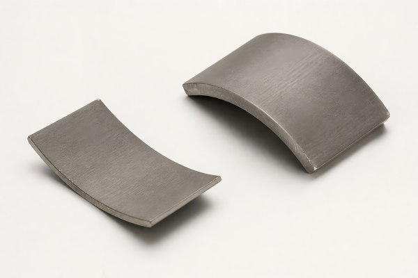
Grade & Orientation
Select isotropic or anisotropic material and the grade family against the real magnetic circuit.
Ningbo Vanguard Technologies Co., Ltd
Drawing-based ceramic magnets for motors, sensors, speakers, holding systems, magnetic separation and high-volume industrial assemblies.
Vanguard reviews material grade, pressing direction, custom geometry, magnetization, grinding, inspection and assembly requirements as one manufacturable specification.
Request a Custom Magnet Review
Customization Snapshot
Select isotropic or anisotropic material and the grade family against the real magnetic circuit.
Define every functional radius, angle, hole, slot, step, chamfer, datum and tolerance.
State magnetization direction, pole count, polarity identification and measurement surface.
Validate tooling, samples, assembly fit and inspection criteria before production release.
Custom Geometry
Use these common shapes as starting points or submit an irregular profile. Custom shape does not automatically define pole direction, so the approved drawing should also identify the magnetic axis, north and south surfaces and test location.


Engineering Selection
Pressing direction, material orientation, draft, wall thickness, radii and grinding access influence what can be made consistently.
Flux, pull force and operating point depend on steel, air gap, pole area, temperature and nearby magnetic components.
Avoid sharp internal corners, thin unsupported sections, point loading and metal-like interference fits. Define acceptable edge chips.
Surface flux and pull force require an agreed probe, distance, fixture, steel target, direction and environmental condition.
Magnetic Performance
Reference values at 20 °C from the existing Vanguard ferrite grade table. The approved material specification and agreed inspection criteria govern each order.
| Grade | Standard | Br mT | Br kG | Hcb kA/m | Hcb kOe | Hcj kA/m | Hcj kOe | BHmax kJ/m³ | BHmax MGOe |
|---|---|---|---|---|---|---|---|---|---|
| Y8T | Chinese | 200-235 | 2.0-2.35 | 125-160 | 1.57-2.01 | 210-280 | 2.64-3.52 | 6.5-9.5 | 0.8-1.2 |
| Y10T | Chinese | 200-235 | 2.0-2.35 | 128-160 | 1.61-2.01 | 210-280 | 2.64-3.52 | 6.4-9.6 | 0.8-1.2 |
| Y20 | Chinese | 320-380 | 3.2-3.8 | 135-190 | 1.70-2.39 | 140-195 | 1.76-2.45 | 18.0-22.0 | 2.3-2.8 |
| Y22H | Chinese | 310-360 | 3.1-3.6 | 220-250 | 2.76-3.14 | 280-320 | 3.52-4.02 | 20.0-24.0 | 2.5-3.0 |
| Y23 | Chinese | 320-370 | 3.2-3.7 | 170-190 | 2.14-2.39 | 190-230 | 2.39-2.89 | 20.0-25.5 | 2.5-3.2 |
| Y25 | Chinese | 360-400 | 3.6-4.0 | 135-170 | 1.70-2.14 | 140-200 | 1.76-2.51 | 22.5-28.0 | 2.8-3.5 |
| Y26H | Chinese | 360-390 | 3.6-3.9 | 220-250 | 2.76-3.14 | 225-255 | 2.83-3.20 | 23.0-28.0 | 2.9-3.5 |
| Y26H-1 | Chinese | 360-390 | 3.6-3.9 | 200-250 | 2.51-3.14 | 225-255 | 2.83-3.20 | 23.0-28.0 | 2.9-3.5 |
| Y26H-2 | Chinese | 360-380 | 3.6-3.8 | 263-288 | 3.30-3.62 | 318-350 | 4.00-4.40 | 24.0-28.0 | 3.0-3.5 |
| Y27H | Chinese | 370-400 | 3.7-4.0 | 205-250 | 2.58-3.14 | 210-255 | 2.64-3.20 | 25.0-29.0 | 3.1-3.6 |
| Y28 | Chinese | 370-400 | 3.7-4.0 | 175-210 | 2.20-2.64 | 180-220 | 2.26-2.76 | 26.0-30.0 | 3.3-3.8 |
| Y28H-1 | Chinese | 380-400 | 3.8-4.0 | 240-260 | 3.02-3.27 | 250-280 | 3.14-3.52 | 27.0-30.0 | 3.4-3.8 |
| Y28H-2 | Chinese | 360-380 | 3.3-3.8 | 271-295 | 3.41-3.71 | 382-405 | 4.80-5.09 | 26.0-30.0 | 3.3-3.8 |
| Y30 | Chinese | 370-400 | 3.7-4.0 | 175-210 | 2.20-2.64 | 180-220 | 2.26-2.76 | 26.0-30.0 | 3.3-3.8 |
| Y30BH | Chinese | 380-390 | 3.8-3.9 | 223-235 | 2.80-2.95 | 231-245 | 2.90-3.08 | 27.0-30.0 | 3.4-3.8 |
| Y30H-1 | Chinese | 380-400 | 3.8-4.0 | 230-275 | 2.89-3.46 | 235-290 | 2.95-3.64 | 27.0-32.0 | 3.4-4.0 |
| Y30H-2 | Chinese | 395-415 | 3.95-4.15 | 275-300 | 3.46-3.77 | 310-335 | 3.90-4.21 | 27.0-32.5 | 3.4-4.1 |
| Y32 | Chinese | 400-420 | 4.0-4.2 | 160-190 | 2.01-2.39 | 165-195 | 2.07-2.45 | 30.0-33.5 | 3.8-4.2 |
| Y32H-1 | Chinese | 400-420 | 4.0-4.2 | 190-230 | 2.39-2.89 | 230-250 | 2.89-3.14 | 31.5-35.0 | 4.0-4.4 |
| Y32H-2 | Chinese | 400-440 | 4.0-4.4 | 224-240 | 2.81-3.02 | 230-250 | 2.89-3.14 | 31.0-34.0 | 3.9-4.3 |
| Y33 | Chinese | 410-430 | 4.1-4.3 | 220-250 | 2.76-3.14 | 225-255 | 2.83-3.20 | 31.5-35.0 | 4.0-4.4 |
| Y33H | Chinese | 410-430 | 4.1-4.3 | 250-270 | 3.14-3.39 | 250-275 | 3.14-3.46 | 31.5-35.0 | 4.0-4.4 |
| Y34 | Chinese | 420-440 | 4.2-4.4 | 200-230 | 2.51-2.89 | 205-235 | 2.58-2.95 | 32.5-36.0 | 4.1-4.5 |
| Y35 | Chinese | 430-450 | 4.3-4.5 | 215-239 | 2.70-3.00 | 217-241 | 2.73-3.03 | 33.1-38.2 | 4.2-4.8 |
| Y36 | Chinese | 430-450 | 4.3-4.5 | 247-271 | 3.10-3.41 | 250-274 | 3.14-3.44 | 35.1-38.3 | 4.4-4.8 |
| Y38 | Chinese | 440-460 | 4.4-4.6 | 285-305 | 3.58-3.83 | 294-310 | 3.69-3.90 | 36.6-40.6 | 4.6-5.1 |
| Y40 | Chinese | 440-460 | 4.4-4.6 | 330-354 | 4.15-4.45 | 340-360 | 4.27-4.52 | 37.5-41.8 | 4.7-5.3 |
| C1 | American | 230 | 2.3 | 148 | 1.86 | 258 | 3.5 | 8.36 | 1.05 |
| C5 | American | 380 | 3.8 | 191 | 2.4 | 199 | 2.5 | 27 | 3.4 |
| C7 | American | 340 | 3.4 | 258 | 3.23 | 318 | 4.0 | 21.9 | 2.75 |
| C8 / C8A | American | 385 | 3.85 | 235 | 2.95 | 242 | 3.05 | 27.8 | 3.5 |
| C8B | American | 420 | 4.2 | 232 | 2.913 | 236 | 2.96 | 32.8 | 4.12 |
| C9 | American | 380 | 3.8 | 280 | 3.516 | 320 | 4.01 | 26.4 | 3.32 |
| C10 | American | 400 | 4.0 | 280 | 3.52 | 284 | 3.57 | 30.4 | 3.82 |
| C11 | American | 430 | 4.3 | 200 | 2.512 | 204 | 2.56 | 34.4 | 4.32 |
| C12 | American | 400 | 4.0 | 290 | 3.65 | 318 | 4.0 | 32 | 4.0 |
Grade selection: Compare values only under equivalent test conditions. Final performance also depends on material orientation, segment geometry, magnetization, motor air gap and the measurement method.
Material Reference
General reference values for sintered ferrite materials. These values describe the material family and are not part-specific acceptance limits unless separately agreed.
| Parameter | Unit | Typical Value |
|---|---|---|
| Density / ρ | g/cm³ | 4.9-5.1 |
| Vickers Hardness / HV | - | 400-700 |
| Compression Strength | N/mm² | 680-720 |
| Coefficient of Thermal Expansion / α | 10-6/°C | C⊥: 10; C∥: 15 |
| Electrical Resistivity / ρ | mΩ·cm | 1 × 10¹⁰ |
| Thermal Conductivity / k | W/(cm·°C) | 0.029 |
| Tensile Strength / σ | Pa | 34 × 106 |
| Modulus of Elasticity / λ | Pa | 1.8 × 10¹¹ |
| Flexural Strength / σ | Pa | 62 × 106 |
| Compression Strength | Pa | 895 × 106 |
| Poisson's Ratio / ν | - | 0.28 |
Orientation notation: C∥ and C⊥ indicate directions parallel and perpendicular to the material orientation axis. Confirm test methods when a physical property is used as a design or acceptance requirement.
Custom Engineering Review
| Design Area | Information to Define | Manufacturing Focus |
|---|---|---|
| Base Geometry | Arc, block, ring, cylinder, sector, trapezoid or irregular profile | Pressing direction, tooling release and material flow |
| Secondary Features | Holes, slots, steps, flats, grooves, chamfers and identification marks | Tooling integration versus diamond grinding |
| Critical Dimensions | Datums, fit dimensions, air-gap surfaces, radii and angle relationships | Sintering variation, grinding stock and inspection access |
| Magnetic Requirement | Grade, orientation, magnetization, poles, flux or pull-force target | Fixture design, saturation and measurement repeatability |
| Assembly Interface | Adhesive gap, housing clearance, steel circuit, clamping and handling | Edge protection, cleanliness and retention |
Supply Options
Combine pressed geometry with diamond-ground pole faces, OD, ID, thickness or other agreed functional dimensions.
Add polarity identification, magnetic sorting, matched sets and lot-level traceability when required.
Review bonding surfaces, adhesive gap, cure method, steel carriers, housings and assembly fixtures.
Define dimensional reports, magnetic records, material certificates, control plans and sample approvals.
Production Support
Control material preparation, field orientation, pressing and sintering against the approved grade and tool.
Use suitable finishing routes for critical surfaces while monitoring chips, cracks and brittle features.
Confirm polarity, pole pattern, grade properties, surface flux or pull force with agreed fixtures.
Maintain approved samples, lot identity, inspection records, packaging standards and change control.
Typical Applications
Custom arcs, sectors and profiles matched to rotor diameter, pole count, air gap and assembly retention.
Special shapes and pole patterns designed around trigger distance, resolution and positional tolerance.
Rings, plates and shaped parts coordinated with steel geometry, voice-coil gap and target field.
Application-specific geometries for steel circuits, housings, working gaps and production assembly.
Project Workflow
Technical Questions
Arcs, blocks, rings, cylinders, sectors, trapezoids and irregular profiles may be reviewed. Feasibility depends on pressing direction, orientation, wall thickness, tooling release and finishing access.
Yes, when compatible with pressing or diamond grinding. Their location, radius, depth, tolerance and effect on part strength must be reviewed.
Tolerance capability is feature-specific. As-sintered and ground dimensions have different capability, cost and inspection requirements.
Multipole or special patterns may be possible depending on geometry, material orientation, size and magnetizing-fixture access. A pole sketch is required.
Bonding, steel carriers, housings, polarity marking, matched sets and selected subassembly work may be supported after design review.
Part complexity, size, orientation, tooling route, magnetizing fixture, grinding, inspection, sample quantity and expected annual volume all affect the quotation.
Send the drawing and application requirements for a custom ferrite magnet review.