Shafts & Rotor Features
Machine bearing journals, shoulders, grooves, threaded ends and locating diameters for motor and motion assemblies.

Ningbo Vanguard Technologies Co., Ltd
Precision shafts, sleeves and rotational components engineered for fit, alignment and repeatability.
Vanguard supports CNC turning from prototypes to repeat production for motor components, magnetic assemblies and industrial equipment. We review the complete relationship between diameters, faces, bores, threads and secondary features.
The correct nominal size is only the start. Functional performance can also depend on roundness, runout, straightness, surface texture and the finished coating condition.

Rotational Geometry
Turning is most effective when critical cylindrical features can be machined and inspected from a consistent rotational reference. Bearing seats, seal diameters, shoulders and bores should be related to the datum axis that matters in the final assembly.
When a part is reversed or moved to another operation, workholding and datum transfer become part of the tolerance stack. Secondary milling or grinding should be planned before the first setup.
Service Scope
Combine turning and secondary operations according to the finished-part drawing.
Machine bearing journals, shoulders, grooves, threaded ends and locating diameters for motor and motion assemblies.
Control OD, ID, wall thickness, end faces and lubrication or retention features for guiding and bearing functions.
Produce steel cups, rotor hubs, pole pieces and cylindrical carriers with assembly-critical interfaces.
Review internal and external threads, sealing faces, wrenching features and final coating or passivation.
Support repeat production of cylindrical hardware with controlled length, chamfers, holes and threads.
Evaluate cross holes, flats, slots and other secondary features for combined machining or a controlled second setup.
Project Workflow
Plan datum relationships, secondary operations and final inspection before cutting stock.
Confirm material, functional axis, fits, threads, finish and quantities.
Define stock, chucking, support, setup sequence and secondary operations.
Select inserts, boring tools, groove tools and thread strategy for the material.
Machine faces, diameters, bores, grooves, threads and approved additional features.
Deburr, clean, surface-treat where required and verify critical characteristics.
Protect journals, threads, coatings and part identification during shipment.
Feature Planning
Size, geometric form and surface texture should be specified as separate requirements.
| Feature | Define on the Drawing | Manufacturing Consideration | Inspection Focus |
|---|---|---|---|
| Bearing Journal | Diameter fit, length, fillet and texture | Support, tool approach and possible grinding allowance | Size, roundness and runout to datum axis |
| Internal Bore | Diameter, depth, bottom form and finish | Bar stiffness, chip evacuation and measurement access | Size, form and relation to external features |
| Shoulder / Face | Axial position, squareness and finish | Tool nose radius, relief and one-setup relationships | Length and face runout |
| Thread | Standard, pitch, class, hand and usable length | Runout, relief, coating allowance and tool access | Specified gauges and thread length |
| Groove | Width, diameter, corner radius and location | Insert geometry, burrs and wall strength | Width, root diameter and axial position |
| Cross Hole / Flat | Position and orientation to the turned axis | Turn-mill access or controlled re-clamping | Angular and positional relationship |
DFM Priorities
Four decisions strongly influence stability, cost and assembly performance.
Long, thin components can deflect or chatter during machining. Review unsupported length, center or steady-rest access, cutting sequence and whether final cylindrical grinding is appropriate.
These terms are not interchangeable. Define the datum axis and the actual geometric or runout control needed by the assembly instead of relying on a general request for concentricity.
State thread system, tolerance class, usable length and gauging method. Provide tool runout and shoulder relief where necessary, and distinguish full bore depth from drill-point depth.
Plating, anodizing and other finishes can change diameters and thread fit. Mark masking zones and clarify whether acceptance applies before or after finishing.
Material Review
Grade, hardness and supplied condition affect chip control, stability and finish.
Confirm grade and heat-treatment sequence. Review distortion, hardness, grinding allowance and corrosion protection.
Account for work hardening, chip control and heat. Identify passivation, sealing and surface finish requirements.
Suitable for lightweight hubs, housings and spacers. Review temper, thin-wall movement and anodizing allowance.
Distinguish free-machining and ductile grades. Consider burrs, conductivity, bearing behavior and protective finish.
Control heat, cutting engagement and tool wear. Feature access and material condition strongly influence feasibility.
Consider creep, moisture, thermal expansion, residual stress and deformation during chucking and measurement.
Quality Planning
Inspection methods are selected for the actual drawing callout and production quantity.
| Control Area | Potential Risk | Verification Approach |
|---|---|---|
| OD / ID Size | Incorrect clearance, interference or press fit | Calibrated micrometers, bore gauges or feature-appropriate measurement. |
| Roundness / Cylindricity | Correct average diameter but unacceptable geometric form | Suitable form measurement where specified. |
| Runout | Bearing, seal or rotating feature misalignment | Datum-based radial or axial runout inspection. |
| Length / Shoulder Position | Incorrect assembly stack or axial location | Controlled face references and calibrated length measurement. |
| Threads | Incorrect pitch, class, usable length or coating allowance | Applicable GO/NO-GO gauges and additional defined checks. |
| Surface & Final Finish | Roughness, burr or coating affects function | Texture, edge, coating and visual checks in the agreed final state. |
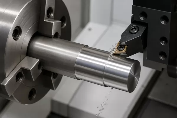
Process Gallery
Representative machining views for shafts and rotational features.

RFQ Preparation
A marked 2D drawing is important for fits, axis relationships and thread requirements.
Drawing revision, 3D model, intended function, mating components and critical interfaces.
Exact grade, hardness or temper, heat treatment, supplied stock and required documents.
Critical OD and ID fits, datums, runout, texture, threads, coating and masking requirements.
Prototype and batch quantities, annual forecast, inspection reports, packaging and target schedule.
Engineering Questions
Share the finished-part drawing and assembly requirements for a feature-level review.
Contact VanguardRotational components such as shafts, sleeves, bushings, hubs, pins, spacers, cups and threaded adapters are typical candidates. Secondary flats, holes or slots can also be reviewed.
No. Achievable limits depend on feature size, material, support, tool access, setup count, finish and inspection. Critical dimensions and geometric relationships should be identified individually.
Define the controlled surface, datum axis and whether radial or axial runout is required. Use the drawing standard appropriate to the project rather than an informal concentricity note.
They can be reviewed, but deflection, chatter, residual stress and handling become important. Support methods, staged cutting or final grinding may be recommended.
Yes, finishing can be coordinated. Specify whether dimensions and threads are accepted before or after coating, plus masking and corrosion requirements.
Provide a revision-controlled 2D drawing and 3D model where available, plus material, quantity, fits, datums, threads, finish and inspection requirements.
Send the drawing, material, finish and quantity for engineering and quotation review.