Housings & Enclosures
Machine pockets, mounting faces, sealing grooves, connector interfaces and threaded features in metal or engineering plastic.

Ningbo Vanguard Technologies Co., Ltd
Precision-machined housings, fixtures and motor components built around functional datums.
Vanguard supports CNC milling from prototype development through repeat production. We review material, geometry, tool access, setup strategy, finishing and inspection as one manufacturing route.
Critical features are planned by function. Hole position, sealing faces, bearing interfaces and magnet pockets each need the right datum and verification method.

Process Strategy
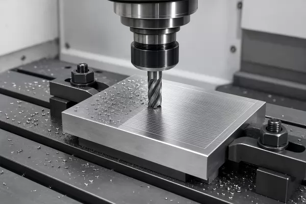
Three-axis milling is efficient for accessible faces, pockets and hole patterns. Fourth- and fifth-axis approaches can improve access to angled or multi-side features and reduce datum transfers, but the best route depends on geometry, quantity and inspection needs.
Fewer setups do not automatically guarantee better parts. Workholding stiffness, tool reach, thermal stability and a clear datum strategy still govern the result.
Service Scope
Features and processes are combined according to the finished drawing.
Machine pockets, mounting faces, sealing grooves, connector interfaces and threaded features in metal or engineering plastic.
Produce hole patterns, slots, counterbores and angled faces from a consistent functional datum structure.
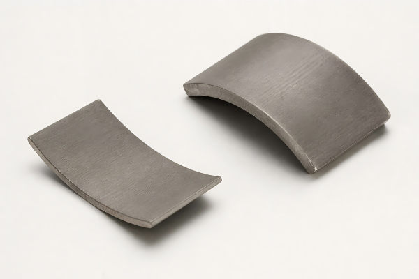
Review magnet carriers, pole supports, rotor or stator fixtures and precision interfaces for assembly alignment.
Build assembly nests, inspection fixtures, positioning blocks and process tooling for development and production.
Machine fins, channels and mounting surfaces while controlling distortion and thermal-interface flatness.
Evaluate indexed or simultaneous multi-axis machining for angled holes, curved surfaces and reduced setup count.
Project Workflow
The route is confirmed before material is released to production.
Confirm material, datums, critical characteristics, finish and quantities.
Review tool access, clamping, stock, internal radii and setup transitions.
Develop toolpaths, select cutters and define in-process controls.
Complete facing, profiling, pockets, drilling, tapping and finishing operations.
Deburr, clean, surface-treat where required and verify the agreed characteristics.
Protect cosmetic and precision surfaces and preserve part identification.
Feature Planning
Tolerance capability is confirmed for the actual feature, material, size and setup strategy.
| Feature | Define on the Drawing | Manufacturing Consideration | Inspection Focus |
|---|---|---|---|
| Datum Face | Flatness and relationship to assembly datums | Stock support, facing sequence and release condition | Flatness and datum establishment |
| Hole Pattern | Size, position, depth and thread requirements | Tool access, drill wandering and setup alignment | Position relative to functional datums |
| Depth, floor, wall and internal radii | Tool reach, chip evacuation and wall stiffness | Depth, wall location and floor condition | |
| Sealing Groove | Cross-section, corner radii and surface requirement | Cutter geometry, burr control and finish sequence | Profile and sealing-surface condition |
| Multi-Side Features | Angular and positional relationships | One-setup multi-axis route or controlled datum transfer | Feature-to-feature relationship |
| Cosmetic Surface | Appearance zone, texture and finish process | Clamping marks, toolpaths and post-treatment variation | Approved visual criteria and finish |
DFM Priorities
Four choices have a strong effect on cost, stability and inspection.
Rotating cutters create an internal radius. Larger corner radii allow stiffer tools and more efficient machining. Deep recesses, undercuts and hidden intersections require an access review.
Long tools can deflect, while thin walls can vibrate or move after unclamping. Increase support where possible and apply tight wall or floor requirements only where function needs them.
Base tolerances on surfaces that locate the finished assembly. When a part must be re-clamped, define how datums transfer between setups and how the final relationship will be inspected.
Anodizing, plating, passivation and blasting change surface condition and sometimes size. State whether dimensions apply before or after finishing and define masking or electrical-contact areas.
Material Review
The exact grade and temper influence tools, workholding, coolant and finishing.
Suitable for lightweight housings, brackets and thermal parts. Review temper, distortion, cosmetic finish and anodizing allowance.
Confirm grade, hardness and heat-treatment sequence. Tool access and stock distribution affect cycle time and distortion.
Review alloy family, work hardening, thin-wall stability, passivation and any sealing or cosmetic requirements.
Account for conductivity, ductility, burr formation and surface protection. Thin fins and delicate features need specific review.
Control heat, tool engagement and part support. Feasibility and delivery depend strongly on geometry and material condition.
Consider creep, moisture, thermal expansion, stress release and clamping deformation during machining and inspection.
Quality Planning
Measurement methods are selected from tolerance, geometry, quantity and reporting needs.
| Control Area | Potential Risk | Verification Approach |
|---|---|---|
| Overall Size & Pocket Depth | Incorrect fit or insufficient wall and floor stock | Calibrated dimensional measurement appropriate to feature access. |
| Hole Position | Fastener or dowel misalignment during assembly | Datum-based CMM or suitable fixture inspection. |
| Flatness & Parallelism | Sealing, heat transfer or stack-up problems | Controlled support and surface measurement against drawing datums. |
| Threads & Inserts | Poor engagement or assembly interference | Specified thread gauges plus insert and usable-depth checks. |
| Surface Texture | Sealing, sliding or appearance requirement not met | Roughness measurement using the specified parameter and direction. |
| Finished Condition | Coating changes fit or masks defects | Inspection after the agreed machining and finishing sequence. |
Process Gallery
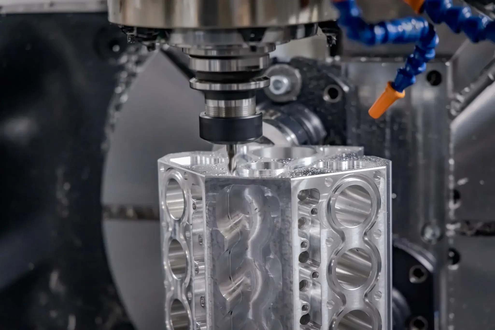
Representative machining views for complex pockets and precision metal features.
RFQ Preparation
A marked 2D drawing remains important even when a 3D model is supplied.
Drawing revision, 3D model, intended function, mating parts and critical interfaces.
Exact grade, temper or hardness, heat treatment, supplied stock and required documentation.
Critical datums, geometric tolerances, texture, coating, masking and cosmetic requirements.
Prototype and batch quantities, annual forecast, inspection reports, packaging and target schedule.
Engineering Questions
Send the drawing and application details for a feature-level review.
Contact VanguardIt is useful for angled features, complex surfaces and multi-side geometry where access or setup reduction provides a clear benefit. Simpler parts may be more economical on 3-axis or indexed equipment.
Tolerance is confirmed by feature after reviewing size, material, tool reach, setup count, finish and inspection. Critical limits should be identified on the drawing rather than assumed from a general capability statement.
Use the largest practical radius. A radius compatible with a shorter, stiffer tool usually reduces cost and improves surface quality. Mating square parts may need corner relief or another design solution.
They can be reviewed, but stiffness, vibration, distortion, tool reach and chip evacuation may limit the practical result. Geometry changes or staged machining may be recommended.
Yes, finishing can be coordinated. The drawing should state whether dimensions apply before or after coating and identify masking, cosmetic and electrical-contact requirements.
Provide a revision-controlled 2D drawing and 3D model where available, plus material, finish, quantities, critical features, inspection requirements and intended use.
Share the drawing, material, finish and quantity for engineering and quotation review.