Bonded Magnet Rotor Assembly
Contact Us Now
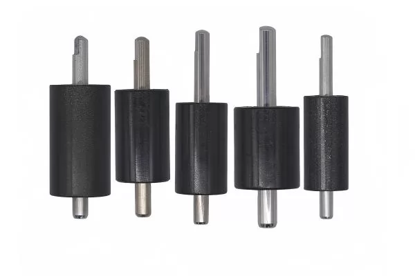
A bonded magnet rotor assembly is a precision rotor module made by integrating bonded magnetic material with a shaft, hub, sleeve, insert, rotor core or molded carrier. Bonded magnets can be compression molded, injection molded or overmolded into complex shapes, making them suitable for compact motors, sensors, pumps, fans and high-volume electromechanical products.
Compared with sintered magnet rotors, bonded magnet rotors offer better geometry flexibility, multi-pole magnetization capability, lower eddy current tendency and fewer separate magnet pieces. The magnetic field, mechanical structure, shaft fit, balance grade and magnetization pattern can be designed together to improve assembly consistency and reduce production workload.
Ningbo Vanguard Technologies supplies custom bonded magnet rotor assemblies using bonded NdFeB, bonded ferrite and hybrid magnetic materials. We support insert molding, overmolding, shaft press-fitting, sleeve assembly, magnetization, dynamic balancing, dimensional inspection and magnetic performance validation for prototype and mass-production projects.
Whether you need a small sensor rotor, pump rotor, fan motor rotor or custom multi-pole rotor assembly, Vanguard can provide engineering review and sample production within 15-25 days after drawing, material, shaft, pole count and test requirements are confirmed.
The following structures are commonly used for bonded magnet rotor assemblies. Final material, pole count, shaft fit and inspection method are confirmed according to drawing and motor performance requirements.
| Rotor Type | Material Option | Typical Pole Count | Core / Insert | Key Feature | Typical Application |
|---|---|---|---|---|---|
| Injection Molded Rotor | Bonded NdFeB / bonded ferrite | 2-48 poles | Shaft, hub, plastic or metal insert | Complex geometry and integrated mounting features | Pumps, fans, appliance motors |
| Compression Molded Rotor | Bonded NdFeB | 2-32 poles | Steel shaft, sleeve, hub | Higher magnetic powder loading and good dimensional stability | BLDC motors, servo devices, sensors |
| Overmolded Shaft Rotor | Bonded NdFeB / ferrite compound | 2-24 poles | Knurled shaft, insert, bearing seat | Strong integration between magnet body and shaft | Small motors, encoders, actuators |
| Multi-Pole Ring Rotor | Bonded NdFeB ring | 4-64 poles | Steel hub or plastic carrier | Stable multi-pole field for sensing and commutation | Encoders, Hall sensors, motor rotors |
| Impeller Rotor | Bonded ferrite / bonded NdFeB | 2-16 poles | Plastic impeller, ceramic shaft, sleeve | Magnet and impeller integrated for sealed pump use | Water pumps, coolant pumps, circulation pumps |
| Custom Molded Rotor | Custom bonded magnetic compound | Custom | Metal, plastic, ceramic or composite insert | Designed around special air gap, speed and package limits | Medical, robotics, research prototypes |
Vanguard can customize bonded magnet rotor assemblies from magnet-only rings to complete shaft-mounted rotor modules. The table below summarizes common specification items for engineering review.
| Item | Available Options | Engineering Notes |
|---|---|---|
| Magnetic Material | Bonded NdFeB, bonded ferrite, hybrid magnetic compound | Selected according to flux output, cost, temperature, shape complexity and production volume. |
| Manufacturing Process | Injection molding, compression molding, overmolding, insert molding | Process choice affects magnetic loading, geometry freedom, tooling cost and production efficiency. |
| Magnetization | Radial, diametrical, axial, multi-pole, skewed pole, custom pattern | Magnetization pattern should match winding design, Hall sensor layout and torque ripple target. |
| Insert / Shaft | Carbon steel, stainless steel, brass, ceramic, plastic, custom hub | Insert material affects strength, corrosion, weight, thermal expansion and magnetic circuit behavior. |
| Assembly Features | Press-fit shaft, molded hub, sleeve, bearing seat, knurl, groove, keyway | Mechanical interface should be reviewed for torque transfer, runout and pull-out strength. |
| Surface Protection | Natural molded surface, epoxy, coating, sleeve, encapsulation | Protection is selected by fluid exposure, wear, humidity, chemical environment and cleanliness. |
| Inspection | Dimension, runout, concentricity, flux, pole angle, balance, pull-out test | Inspection method is customized by motor speed, sensor accuracy and assembly risk. |
| Factor | Influence on Performance | Recommended Check |
|---|---|---|
| Magnetic Loading | Higher powder loading improves magnetic output but may affect molding flow and toughness. | Balance Br, mechanical strength and process stability during material selection. |
| Air Gap | Rotor OD tolerance and runout directly affect flux density and motor efficiency. | Confirm OD tolerance, concentricity and rotor-stator clearance. |
| Pole Accuracy | Pole angle error can affect torque ripple, sensor signal and commutation accuracy. | Define pole angle, surface flux and flux waveform inspection requirements. |
| Operating Speed | High speed increases requirements for balance, insert retention and material strength. | Specify speed, balance grade and any burst or pull-out test requirement. |
| Temperature / Fluid | Heat, coolant, oil or water exposure may affect resin and magnet stability. | Select suitable resin, coating or sleeve protection for the environment. |
Vanguard can customize bonded magnet rotor outer diameter, inner diameter, shaft size, pole count, magnetization pattern, molded structure, insert material, coating, balance grade and inspection method. For new motor projects, we can support prototype rotors for magnetic validation before production tooling.
Assembly support: We provide compound selection, insert molding, shaft press-fitting, sleeve assembly, magnetization, polarity marking, flux inspection, runout control and dynamic balancing.
Engineering review: If the project involves high speed, fluid exposure, tight sensor signal tolerance or high-volume automation, our engineering team can review tooling, material and inspection requirements before sampling.
Production begins with rotor drawing review, compound selection and tooling design. Inserts, shafts or hubs are prepared with surface treatment when required, then bonded magnetic material is molded, pressed or overmolded into the required rotor shape.
Finished rotors are magnetized, checked for polarity and magnetic waveform, inspected for dimension and runout, balanced when required, and packed with anti-collision protection for shipment.
Magnetic inspection: Surface flux, flux waveform, pole angle, polarity, magnetization direction and flux mapping can be checked by requirement.
Dimensional control: OD, ID, height, shaft fit, concentricity, runout, molded shrinkage, bearing seat and appearance are inspected per drawing.
Mechanical validation: Dynamic balance, pull-out strength, torque transfer, heat aging, fluid exposure and vibration-related checks can be arranged for critical projects.
Documentation: Material certificate, inspection report, magnetic test data, RoHS/REACH declaration and lot traceability records are available.
To speed up engineering review, please provide a 2D/3D drawing or confirm the specifications below. If the design is still under development, Vanguard can help compare bonded NdFeB, bonded ferrite, injection molding and compression molding options before sampling.