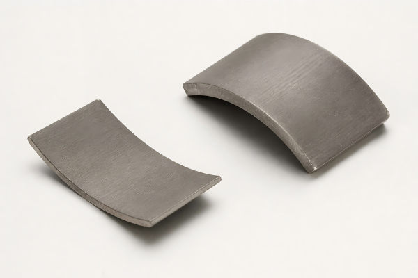
Compact BLDC Motor
For space-limited mechanisms and compact motor modules.
- Envelope and shaft geometry
- Voltage and operating speed
- Load profile and thermal limits
Ningbo Vanguard Technologies Co., Ltd
Brushless DC motor solutions, from components to complete assemblies.
Bring your motor requirements to one engineering discussion. Vanguard supports magnetic materials, rotor and stator components, prototype development and manufacturing planning for application-specific BLDC motor projects.
Start with the load, speed range and installation envelope. Together, we can define the motor configuration, validation targets and supply scope.

A coordinated design of rotor, stator, bearings, shaft and housing.

Magnetic grade, pole arrangement, retention and balancing requirements.
Lamination geometry, winding configuration, insulation and thermal path.
Shaft, bearings, mounting features, housing and electrical connections.
Three enquiry starting points. Final ratings and dimensions are confirmed against your application.
For space-limited mechanisms and compact motor modules.

For continuous-duty equipment where the operating point and cooling conditions must be assessed together.

For projects requiring a coordinated motor, feedback and mechanical interface.
Motor selection starts with the operating conditions of the complete machine.

Translate acceleration, wheel load and speed targets into motor-side torque and duty requirements. Review any gearbox, brake and feedback interfaces together.

Define operating noise, movement profile, standby behavior and installation space for actuators and automated mechanisms.

Review start-up load, intermittent overloads, enclosure protection and cooling for outdoor drive systems.
Engineering support across magnetic materials, motor components and production.
Define torque, speed, duty cycle and mechanical limits before selecting a motor configuration.
Coordinate magnets, rotor geometry, stator laminations and windings against the application requirements.
Plan samples around measurable targets, drawings and a clear validation process.
Review shafts, bearings, housings, feedback devices and controller connections as one assembly.
Align critical dimensions, assembly steps, inspection methods and change control for repeat orders.
Connect engineering decisions with sourcing, sample feedback and production planning.
A clear operating point makes technical review and quotation more effective.
| Requirement | Information to Provide | Engineering Purpose |
|---|---|---|
| Power Supply | Nominal DC voltage and minimum/maximum supply voltage | Review winding and controller compatibility. |
| Torque & Speed | Continuous operating points, peak torque and peak duration | Distinguish rated operation from temporary overload. |
| Duty & Cooling | Load cycle, ambient temperature, mounting and cooling method | Establish the thermal conditions for continuous performance. |
| Mechanical Envelope | Motor diameter, length, shaft, flange and bearing loads | Define installation and component interfaces. |
| Control & Feedback | Controller scope, Hall signals or encoder, wiring and connectors | Confirm commutation, start-up and control requirements. |
| Validation & Supply | Test criteria, sample quantity, annual demand and target dates | Agree acceptance criteria and the development schedule. |
Mechanical output power: P (W) = T (N·m) × 2π × n (rpm) / 60. Compare ratings at the same duty cycle and thermal conditions.
Simulation
Discuss magnetic and thermal questions before committing to hardware.
FEA SimulationPrototyping
Translate drawings and performance targets into a focused sample plan.
Rapid PrototypingProduction
Define critical process steps, inspection requirements and change control.
Manufacturing Process ControlHelp Center
Discuss your operating requirements with our team.
Contact VanguardA brushless DC motor uses electronic commutation to drive a permanent-magnet rotor. A compatible controller switches the winding currents using rotor-position information from sensors or an estimation method.
Provide supply voltage and its operating range, the required torque-speed points, duty cycle, mounting space and cooling conditions. Include peak loads, ambient temperature and feedback requirements where known.
Share your application or existing drawing for review. The scope can cover magnetic materials, rotor and stator components, prototype assemblies and a complete motor development program, subject to the agreed specification.
Yes. Controller voltage, current, commutation method and feedback interfaces must match the motor and application. Specify whether the enquiry covers a motor only or a motor-and-controller system.
Mechanical output power is P = T × 2πn / 60, where P is in watts, torque T is in N·m and speed n is in rpm. Electrical input power is higher than shaft output because of losses; continuous performance also depends on cooling and duty.
Lead time depends on the design, tooling, component availability, test scope and quantity. Supply the sample deadline and expected annual volume so the project schedule can be confirmed during quotation.
Send your drawing, voltage, torque-speed requirements and planned quantity.