Product Overview
Axial Flux Rotor Assembly
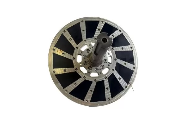
Axial flux rotor assemblies are high-performance magnetic rotor modules used in axial flux motors and generators. Compared with conventional radial flux motor structures, axial flux designs place the magnetic flux path along the shaft direction, allowing a shorter axial length, higher torque density and a compact disc-shaped motor structure.
A typical axial flux rotor assembly includes a precision rotor back plate, high-performance permanent magnets, bonding adhesive, optional retaining ring, protective coating or potting layer, and final magnetic and mechanical inspection. The assembly quality directly affects motor torque output, cogging behavior, vibration, noise, efficiency and long-term reliability.
Ningbo Vanguard Technologies supplies custom axial flux rotor assemblies using NdFeB, SmCo or ferrite magnets according to motor power, operating temperature, speed, corrosion environment and cost target. We support rotor design review, magnet grade selection, polarity layout, bonding process development, dynamic balancing, magnetic field testing and batch production.
Whether you need prototype rotors for motor validation or stable mass production for OEM projects, Vanguard can provide sample assembly within 10–20 days after drawing and specification confirmation, with full inspection records available upon request.
Quick View
Axial Flux Rotor Assembly Selection Snapshot
Disc Rotor
Compact Motor Topology
Short axial length and high torque density for axial flux motors and generators.
NdFeB / SmCo
Magnet Material Options
Grade is selected by torque target, temperature, speed and demagnetization margin.
Balance
Mechanical Control
Runout, flatness, concentricity and dynamic balance help reduce vibration and noise.
10-20 Days
Prototype Lead Time
Fast sampling after rotor drawing, magnet layout and inspection method are confirmed.
Rotor Design Focus
Magnet Retention
Critical
1Rotor ReviewDiameter, thickness, pole count
2Grade MatchBr, Hcj, temperature
3Bonding PlanAdhesive, fixture, retention
4Assembly CheckPolarity, runout, balance
5Final ReportFlux, size, appearance
Key Applications
Axial Flux Motors
Rotor assemblies for compact high-torque axial flux motors used in e-mobility, industrial drives, traction systems and lightweight power units.
EV & E-Mobility
High-energy NdFeB rotor modules for electric motorcycles, scooters, light EV platforms, in-wheel motors and compact traction motor systems.
Generators
Axial flux generator rotors for wind power, hydro power, portable generators and low-speed direct-drive energy systems.
Robotics & Servo Drives
Thin rotor assemblies for robot joints, torque motors, precision actuators and compact servo systems requiring high torque in limited space.
Industrial Equipment
Custom rotor assemblies for pumps, compressors, fans, automation equipment and special-purpose electric machines.
Prototype Motor R&D
Small-batch custom rotor assemblies for universities, laboratories, startups and engineering teams developing new motor platforms.
Typical Assembly Specifications
The following values are typical options for custom axial flux rotor assemblies. Final dimensions, materials and inspection standards are confirmed according to drawings, motor design, working speed, torque target and operating environment.
|
Item |
Available Options |
Engineering Notes |
|
Rotor Type |
Single rotor, dual rotor, inner stator, outer rotor, sandwich structure |
Selected according to motor topology, air gap, torque density and assembly space. |
|
Magnet Material |
NdFeB, SmCo, ferrite |
NdFeB offers high torque density; SmCo suits high temperature; ferrite is economical for low-cost designs. |
|
Magnet Shape |
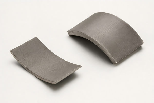
Arc segment, trapezoid, rectangular block, sector, custom profile |
Shape can be optimized for pole coverage, flux distribution and cogging reduction. |
|
Magnetization |
Axial, radial-assisted, parallel, multipole, Halbach array |
Magnetization pattern is designed according to target air-gap flux and back-EMF waveform. |
|
Rotor Back Plate |
Carbon steel, stainless steel, aluminum alloy, custom machined plate |
Material choice affects magnetic circuit, strength, weight, corrosion protection and balance quality. |
|
Bonding Method |
Structural adhesive, positioning fixture bonding, vacuum potting, mechanical retaining |
Bonding process is validated by temperature, speed, centrifugal force and vibration requirements. |
|
Surface Protection |
NiCuNi, epoxy, Zn, phosphate, parylene, potting resin, sleeve protection |
Protection is selected based on humidity, salt spray, oil exposure and handling conditions. |
|
Balancing |
Static balance, dynamic balance, customer-specified grade |
Recommended for high-speed rotors to reduce vibration, noise and bearing load. |
|
Inspection |
Dimension, polarity, flux, pull force, runout, concentricity, adhesive coverage, balance |
Inspection records can be provided for prototype validation and mass-production control. |
Magnet Material & Grade Selection
|
Material |
Common Grade Range |
Temperature Capability |
Best Used For |
|
NdFeB |
N35-N52, N35M-N50M, N35H-N48H, N35SH-N45SH, UH/EH series |
Approx. 80-200 °C depending on grade |
High torque density, compact motors, EV traction, robotics and lightweight generators. |
|
SmCo |
SmCo5, Sm2Co17 series |
Approx. 250-350 °C depending on grade |
High-temperature motors, aerospace systems, vacuum or harsh-environment applications. |
|
Ferrite |
Y30, Y30BH, Y35, C5, C8 |
Approx. 200-250 °C depending on grade |
Cost-sensitive axial flux generators, education motors and large low-speed assemblies. |
Selection note: For high-speed axial flux rotors, magnet grade should be confirmed together with operating temperature, demagnetization risk, air-gap flux requirement, centrifugal force and coating durability. Vanguard can recommend a grade after reviewing the rotor drawing and motor working conditions.
Available Assembly Configurations
Surface-Mounted Rotor
Permanent magnets are bonded on the rotor back plate with controlled pole spacing. This is a common structure for compact axial flux motors and generators.
Dual-Rotor Assembly
Two magnet rotors operate on both sides of the stator to increase torque density and improve utilization of the magnetic circuit.
Halbach Rotor
A customized magnetization arrangement strengthens the air-gap field on one side and reduces leakage flux on the back side.
Potted Rotor Module
Magnets are bonded and sealed with resin to improve moisture resistance, insulation, impact protection and handling safety.
Retaining-Ring Rotor
A mechanical retaining structure is added for higher-speed applications where centrifugal force and long-term adhesive strength must be carefully controlled.
Prototype Rotor Kit
Small-batch assemblies with marked polarity, inspection report and packaging by set for engineering validation and motor testing.
Design Points for Axial Flux Rotors
Axial flux rotor assemblies require both magnetic performance and mechanical reliability. During design review, Vanguard focuses on pole pair number, magnet coverage, air-gap flux density, magnet thickness, steel back plate saturation, adhesive shear strength, temperature rise, corrosion protection and rotor balance.
For high-speed applications, magnet retention is especially important. We can evaluate bonding area, adhesive type, potting design, edge chamfer, fixture positioning and optional mechanical retaining methods to reduce the risk of magnet movement during operation.
Magnetic Layout
Pole count, polarity sequence, Halbach arrangement, magnet spacing and air-gap flux can be customized according to motor design.
Mechanical Strength
Rotor speed, centrifugal force, adhesive strength, retaining ring and potting structure are reviewed for safe operation.
Thermal Stability
Magnet grade, coating and adhesive are selected according to continuous temperature, peak temperature and demagnetization margin.
Assembly Accuracy
Pole position, flatness, runout, concentricity and balance are controlled to reduce torque ripple, vibration and noise.
Manufacturing & Quality Assurance
Our axial flux rotor assembly process includes incoming magnet inspection, rotor plate machining check, surface cleaning, fixture positioning, adhesive dispensing, magnet placement, curing, polarity verification, flux testing, dimensional inspection, optional potting, balance inspection and final packaging.
|
Process Step |
Control Target |
Typical Inspection Method |
|
Magnet Inspection |
Grade, size, coating, polarity and magnetic strength |
Gauss meter, flux meter, caliper, coating check and visual inspection. |
|
Rotor Plate Inspection |
Flatness, concentricity, hole position, surface condition |
CMM, height gauge, runout gauge and drawing-based dimensional check. |
|
Bonding & Curing |
Adhesive coverage, magnet position, curing time and temperature |
Assembly fixture, visual check, process record and sample strength validation. |
|
Magnetic Verification |
Polarity sequence, field distribution and output consistency |
Polarity checker, surface Gauss test, flux test or customer-defined magnetic scan. |
|
Final Assembly Check |
Runout, balance, appearance, marking and packaging by set |
Dial indicator, balancing equipment, visual inspection and packing checklist. |
Available Custom Features
Custom Rotor Diameter
Outer diameter, inner bore, bolt holes, locating holes and plate thickness can be produced according to your drawings.
Custom Pole Count
Pole number, pole pair arrangement and polarity sequence can be matched to your stator winding and controller design.
Magnet Shape Optimization
Arc, sector, trapezoid, block and custom magnet profiles are available for flux optimization and assembly convenience.
Surface Treatment
Nickel, epoxy, zinc, phosphate, passivation, black epoxy, potting and other protection options can be selected by environment.
Polarity Marking
N/S marking, laser marking, color marking, arrow marking and assembly orientation labels can be provided for easy installation.
Inspection Report
Dimensional report, magnetic report, coating report, balance report and batch traceability documents are available upon request.
Information Needed for Fast Quotation
To quote an axial flux rotor assembly quickly, please provide rotor drawing, outer diameter, inner bore, thickness, magnet quantity, magnet size, pole count, magnet material or target flux, operating speed, working temperature, coating requirement, balancing requirement, annual quantity and any special testing standard.
If the design is still under development, you may share the motor power, torque target, speed range, air-gap size, available assembly space and operating environment. Our engineering team can help recommend a practical magnet material, grade and rotor assembly method.
Frequently Asked Questions
Can you produce axial flux rotor assemblies according to our drawing?
Yes. We can manufacture custom rotor plates, supply matched magnets, design assembly fixtures, bond magnets, verify polarity and provide final inspection according to your drawing and technical requirements.
Which magnet material is best for an axial flux rotor?
NdFeB is the most common choice for high torque density and compact motor size. SmCo is recommended for higher-temperature or harsh environments. Ferrite can be used when cost is more important than compactness.
Can you make Halbach axial flux rotor assemblies?
Yes. We can produce Halbach or customized polarity arrangements after confirming the magnetization direction, magnet shape, pole sequence and assembly fixture requirements.
How do you prevent magnets from coming loose at high speed?
We review rotor speed, magnet mass, bonding area, adhesive type, curing process, potting structure and optional retaining design. For demanding applications, dynamic balance and mechanical retention are recommended.
Can you provide magnetic field or flux test data?
Yes. Surface Gauss, total flux, polarity sequence, flux consistency and customer-defined magnetic scan data can be provided depending on the project requirement and testing method.
What is the lead time for custom axial flux rotor assemblies?
Prototype lead time is usually 10-20 working days after drawing and specification confirmation. Mass-production lead time is typically 25-45 working days depending on rotor size, magnet grade, tooling, inspection requirements and order quantity.