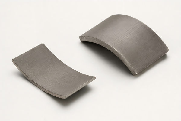
Axial Flux Laminations
Contact Us Now
Axial flux laminations are precision magnetic core components used in axial flux motors, axial flux generators and compact high-torque electric machines. Unlike radial flux motors, axial flux machines guide magnetic flux along the motor axis, so lamination geometry, core segmentation, flatness, insulation and stack accuracy are critical for torque density and efficiency.
Axial flux cores may use segmented electrical steel laminations, spirally wound strip laminations, soft magnetic composite cores, tooth segments or custom bonded stacks. The best structure depends on flux direction, operating frequency, air gap, cooling method, winding layout, axial force and manufacturing volume.
Ningbo Vanguard Technologies supplies custom axial flux laminations and core assemblies using low-loss electrical steel, silicon steel, SMC materials and custom magnetic alloys. We support prototype cutting, stamping, segmented stack assembly, bonding, welding, insulation review, flatness control and dimensional inspection.
Whether you need prototype axial flux core segments for motor validation or production lamination stacks for axial flux assembly, Vanguard can provide engineering review and sample production within 10-30 days after drawing, material grade, stack height and tolerance requirements are confirmed.
The following core structures are commonly used in axial flux motor projects. Final material, geometry, stack height and tolerance are confirmed according to drawing and electromagnetic design requirements.
| Core Type | Typical Material | Thickness / Process | Stacking Method | Key Feature | Typical Application |
|---|---|---|---|---|---|
| Segmented Tooth Stack | Non-oriented electrical steel | 0.20-0.50 mm | Bonded, welded, fixture assembled | Good winding access and flexible pole layout | Axial flux motors, EV drives |
| Ring Lamination Stack | Silicon steel / low-loss steel | 0.20-0.50 mm | Interlock, weld, bond | Continuous magnetic path and stable geometry | Generators, compact motors |
| Spiral Wound Core | Electrical steel strip | Strip wound process | Winding and bonding | Reduced waste for circular core structures | Axial flux generators, motor cores |
| SMC Axial Core | Soft magnetic composite | Powder metallurgy process | Pressed and heat treated | Supports 3D flux path and complex tooth shapes | Compact axial flux motors |
| Prototype Laser-Cut Core | Silicon steel / custom alloy | 0.20-0.50 mm | Loose or bonded prototype stack | Fast validation before production tooling | Motor R&D and sample testing |
| Double-Sided Stator Core | Electrical steel / SMC | Custom | Segmented or ring assembly | Designed for dual rotor axial flux machines | High torque-density motors |
Vanguard can customize axial flux core segments, prototype stacks and production lamination assemblies. The table below summarizes common specification items for engineering review.
| Item | Available Options | Engineering Notes |
|---|---|---|
| Material | Electrical steel, silicon steel, low-loss alloy, SMC, custom core material | Selected according to flux path, frequency, saturation, loss and manufacturing method. |
| Core Structure | Segmented tooth, ring stack, spiral wound core, SMC core, custom profile | Structure should match winding layout, air gap, cooling method and production volume. |
| Thickness | 0.20 mm, 0.27 mm, 0.35 mm, 0.50 mm or custom | Thin laminations reduce loss but may increase stack complexity and cost. |
| Manufacturing Process | Laser cutting, stamping, progressive die, powder pressing, bonding | Prototype and mass-production processes may differ for cost and tolerance reasons. |
| Stacking Method | Loose stack, bonding, welding, interlocking, fixture assembly | Stacking method affects flatness, strength, insulation and magnetic loss. |
| Critical Geometry | OD, ID, tooth pitch, axial thickness, flatness, parallelism, air-gap surface | Axial flux machines require careful control of flatness and air-gap-facing surfaces. |
| Inspection | Dimension, burr height, flatness, stack height, segment pitch, coating condition | Inspection method is customized by motor structure and air-gap requirement. |
| Factor | Influence on Performance | Recommended Check |
|---|---|---|
| Air Gap Flatness | Uneven axial surfaces can cause force imbalance, noise and efficiency loss. | Define flatness, parallelism and stack height tolerance. |
| Core Material | Material controls saturation, loss and thermal behavior. | Choose electrical steel, SMC or custom alloy according to flux path and frequency. |
| Segment Pitch | Position error can affect torque ripple and electromagnetic balance. | Use assembly fixtures and inspection for segment position. |
| Burr / Insulation | Burr or damaged insulation can increase eddy current loss and heat. | Define burr limit and insulation condition requirements. |
| Stacking Method | Bonding, welding and fixture assembly affect strength and loss differently. | Select method according to speed, temperature and assembly process. |
Vanguard can customize axial flux core outer diameter, inner diameter, tooth shape, segment angle, axial height, stack method, material grade, sheet thickness, flatness requirement and inspection standard. For new motor projects, we can support prototype core sets before production tooling investment.
Process support: We provide laser-cut samples, segmented stack assembly, stamping production, bonding, welding, SMC core review, stack height control and protective packaging.
Engineering review: If the project involves dual rotors, high torque density, thin air gap or high efficiency, our engineering team can review material, insulation, flatness and stack process before sampling.
Production begins with magnetic circuit review, material selection and process planning. Prototype axial flux cores can be laser cut, segmented and fixture assembled, while mass production may use stamping, progressive tooling, bonding, welding or SMC pressing depending on geometry and volume.
Finished core assemblies are inspected for dimensions, segment position, burr, stack height, flatness, parallelism and appearance before packaging.
Dimensional inspection: OD, ID, segment angle, tooth width, axial thickness, stack height, flatness and parallelism are checked per drawing.
Process inspection: Burr height, flatness, stacking direction, weld position, bonding condition and segment assembly quality can be inspected by requirement.
Material verification: Electrical steel grade, sheet thickness, insulation coating, SMC material and material certificate can be provided for traceability.
Documentation: Material certificate, inspection report, dimensional report, RoHS/REACH declaration and lot traceability records are available.
To speed up engineering review, please provide a 2D/3D drawing or confirm the specifications below. If the axial flux core is still under development, Vanguard can help compare segmented electrical steel, ring lamination and SMC options before sampling.