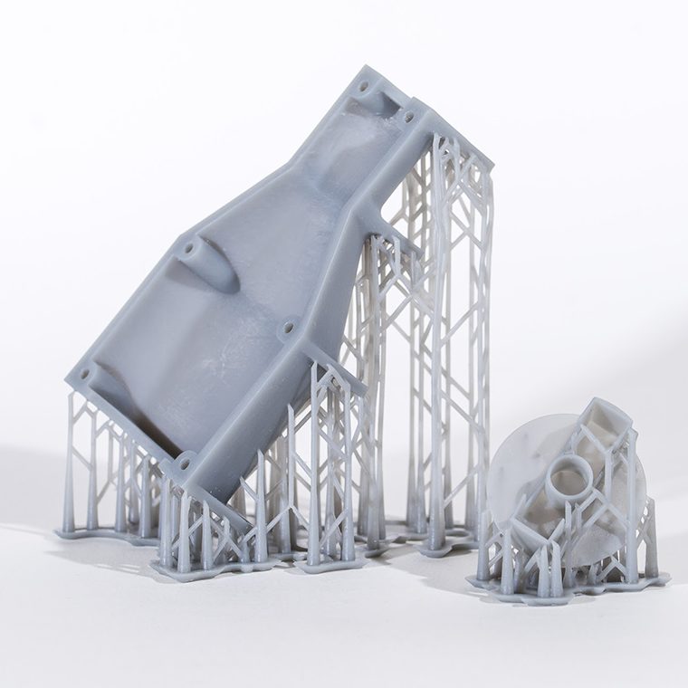
SLA Resin Printing
Fine details and smooth surfaces for visual models, housings, master patterns and fit-check prototypes.
Engineering Services
Industrial additive manufacturing for design verification, functional testing and low-volume production.
Vanguard supports 3D printed parts for motor development, magnetic assembly fixtures, housings, ducts, brackets, test equipment and custom industrial components. We select the printing process from the part's real purpose, then coordinate orientation, supports, finishing, inserts, inspection and assembly.


Purpose Before Process
A visual model, assembly-check sample and load-bearing prototype may require different processes even when they share the same geometry. Surface finish, strength, heat resistance, dimensional stability and cost must be ranked before printing.
We review critical interfaces and build direction before quotation. Holes, sealing faces, threads, bearing seats and inspection datums may need allowance, inserts or secondary machining rather than relying on as-printed dimensions.
Process Capability
Process selection is based on function, geometry, material behavior, finish, quantity and budget.
Fine details and smooth surfaces for visual models, housings, master patterns and fit-check prototypes.
Support-free powder-bed production for functional PA11 or PA12 parts, clips, brackets and complex assemblies.
Functional nylon parts with useful batch consistency for prototypes, fixtures and low-volume component supply.
Cost-effective production of larger models, jigs and simple functional parts in thermoplastic materials.
Complex metal geometries, internal channels and lightweight structures with planned heat treatment and machining.
Support removal, curing, sanding, dyeing, painting, tapping, threaded inserts, machining and functional assembly.
Project Workflow
The print plan is tied to the prototype question and its acceptance criteria.
Confirm the test objective, geometry, quantities, interfaces, loads, finish and target schedule.
Compare feasible processes and materials for accuracy, strength, appearance, size and total cost.
Set orientation, nesting, supports, compensation and allowance for critical post-machined features.
Control the build, remove supports or powder, clean the parts and complete required curing.
Finish surfaces, dye or paint, machine datums, install inserts and assemble related components.
Check critical dimensions and fit, document results and feed findings into the next design iteration.
Selection Guide
Values below are general planning guidance, not guaranteed tolerances. Part size, geometry, orientation and post-processing can change the result.
| Process | Common Materials | Best Fit | Surface & Detail | Key Limitation |
|---|---|---|---|---|
| SLA | Standard, tough, clear and heat-resistant photopolymers | Visual models, fine housings and masters | Smooth surface and fine detail | Properties can be direction-, cure- and aging-sensitive. |
| SLS | PA12, PA11 and filled nylon | Functional brackets, clips and ducts | Uniform matte powder texture | Porosity, roughness and dimensional drift require consideration. |
| MJF | PA12, PA11 and TPU options | Functional batches and production-like prototypes | Fine textured surface, commonly dyed | Color and finish choices depend on process and supplier. |
| FDM / FFF | PLA, ABS, PETG, PC, nylon and reinforced filament | Large models, fixtures and simple parts | Visible layer lines | Anisotropy, support marks and warpage can be significant. |
| Metal LPBF | Stainless steel, aluminum, titanium and nickel alloys | Complex metal parts and internal passages | As-built surface usually needs finishing | Support, heat treatment, distortion and machining add cost. |
| Hybrid Print + Machine | Polymer or metal printed preforms | Bearing seats, datums, threads and sealing faces | Critical surfaces finished by machining | Requires suitable machining allowance and workholding. |
Design Review
Geometry should support the printing process and the intended verification task.
Minimum walls, pins, slots and embossed text depend on process, material, part scale and orientation. Thin features need explicit review.
Build direction influences strength, support marks, stair stepping, distortion and inspection results. Align load paths deliberately.
Add process-appropriate clearance. Critical bores, threads, sealing faces and bearing seats may need inserts or machining.
Provide access for support removal, trapped resin or powder evacuation, cleaning and inspection of internal passages.
Application Value
Additive manufacturing is most useful when it shortens a specific engineering learning cycle.
Assembly nests, polarity-control aids and adhesive-bonding fixtures for rotor and magnetic assembly trials.
Packaging models and functional enclosures for fit, cable routing, airflow and service-access checks.
Winding guides, handling nests, stack fixtures and checking tools for prototype build activities.
Ducts, manifolds and complex passages used to evaluate thermal-management concepts before hard tooling.
Sensor mounts, drill guides, alignment blocks and custom interfaces for laboratory and production testing.
Service parts, pilot-build components and specialized equipment parts where tooling cannot be justified.
Quality Planning
Acceptance criteria should match the purpose of the prototype instead of relying on a generic printer specification.
| Control Area | Potential Risk | Recommended Evidence |
|---|---|---|
| Input Geometry | Mesh errors, lost features or unintended scaling | File integrity review, revision control and nominal dimension check. |
| Material & Batch | Wrong resin or powder condition and inconsistent properties | Material identification, batch traceability and supplier data. |
| Orientation & Supports | Weak load direction, support scars or distortion | Approved build orientation and support plan. |
| Post-Processing | Dimensional change, incomplete cure or finish variation | Controlled curing, cleaning, finishing and machining instructions. |
| Critical Dimensions | Assembly interference or failed functional fit | Drawing-defined datums, calibrated inspection and fit checks. |
| Functional Validation | Prototype passes appearance review but fails the intended test | Load, temperature, leak, assembly or endurance test tied to purpose. |
Process Examples
Images show representative additive manufacturing outputs and applications.


RFQ Support
Send the model and explain what the part must prove. That usually matters more than naming a preferred printing technology.
Contact VanguardUse SLA when appearance and fine detail lead, SLS or MJF for functional nylon parts, FDM for economical larger fixtures, and metal AM for complex metal geometries. Final selection depends on the actual test and acceptance criteria.
Yes, provided the material, orientation, environment and load case are appropriate. Printed material data should not automatically be treated as identical to molded or wrought material data.
Provide STEP data where possible, plus a drawing identifying critical dimensions, quantity, application, material needs, finish, color, loads, temperature and required delivery date.
Accuracy varies with process, size, geometry, orientation, material and finishing. Critical interfaces should be identified for measurement, compensation, inserts or secondary machining.
Yes. Heat-set inserts, tapping, reaming, milling and other secondary work can be planned where the geometry and material allow.
Review another process when volume, unit cost, material performance, surface finish, tolerance or repeatability can no longer be met efficiently by printing.
Send the 3D model, quantity, application, material, finish and critical dimensions for an engineering review.