Custom Magnetization Direction for Motor Magnets
Ningbo Vanguard Technologies Co., Ltd
Custom Magnetization Direction for Motor Magnets
Engineering guidance for choosing axial, radial, diametric, multipole and arc magnetization directions in permanent magnet motors, magnetic couplings, sensors and custom magnetic assemblies.
Why Magnetization Direction Defines Motor Performance
Magnet material and grade are only part of a motor magnet specification. The magnetization direction determines how flux enters the air gap, how poles align with the stator, how torque is produced and how stable the magnetic circuit remains under temperature and reverse field.
For motor engineers, magnetization should be defined together with pole count, rotor topology, air gap, magnet shape, assembly method and inspection plan. A correct drawing should show not only magnet dimensions and coating, but also the required magnetic orientation and polarity sequence.
Selection Snapshot
Axial MagnetizationCommon for discs, cylinders, blocks and assemblies where flux passes through the magnet thickness.
Radial MagnetizationUsed for ring magnets and rotor structures where flux must point toward or away from the shaft center.
Diametric MagnetizationUseful for sensor rotors, small motor parts and cylindrical magnets requiring north-south poles across diameter.
Multipole MagnetizationApplied to rings, discs and tracks when multiple alternating poles are required on one surface.
Motor Magnetization Must Match the Magnetic Circuit
Surface-mounted rotors often use arc magnets with radial or parallel magnetization depending on rotor diameter, pole count and manufacturing feasibility. Interior permanent magnet rotors may require block magnets with carefully controlled orientation inside slots. Sensor rings and encoder magnets often use multipole magnetization on the outer diameter or end face.
NdFeB magnets are frequently used where high torque density is required. SmCo magnets are chosen for high-temperature stability. Ferrite magnets support cost-sensitive and bonded magnet applications. AlNiCo is mainly selected for special temperature or sensor conditions. In all cases, magnetization direction must be measurable and repeatable in production.
Engineering note: A magnet drawing that only says "magnetized" is not sufficient for motor production. The drawing should specify direction, pole surface, polarity sequence and acceptable magnetic inspection method.
Magnetization Options Compared
| Magnetization Type | Typical Magnet Shape | Motor or Assembly Use | Design Concern | Inspection Method |
|---|---|---|---|---|
| Axial | Disc, cylinder, block, ring | Axial flux rotors, holding magnets, sensor targets | Air gap direction and pole face must match assembly layout | Gaussmeter check on flat pole face |
| Radial | Ring, arc segment, rotor sleeve assembly | BLDC rotors, PMSM rotors, magnetic couplings | Fixture cost, ring size limit and radial field uniformity | Radial flux scan and polarity map |
| Diametric | Cylinder, ring, small rotor magnet | Sensor rotors, miniature motors, position detection | Orientation mark and assembly angle control are critical | Hall probe or compass polarity check |
| Multipole | Ring, disc, bonded magnet, magnetic track | Encoders, stepper motors, linear motors, fan rotors | Pole pitch tolerance, waveform and magnetizing fixture design | Magnetic field mapping and pole count verification |
| Skewed or custom pattern | Rotor segments, Halbach arrays, custom assemblies | Noise reduction, torque ripple control, focused field designs | Higher engineering and fixture validation requirement | 3D field scan or application-level performance test |
Recommended Engineering Workflow
1Define TopologyConfirm radial flux, axial flux, linear motor, coupling, sensor or special magnetic assembly.
2Set Pole LayoutDefine pole count, pole pitch, polarity sequence and required flux direction.
3Choose Magnet FormSelect arc, ring, block, cylinder, bonded magnet or custom geometry.
4Validate FixtureCheck whether the magnetizing fixture can achieve the required field strength and pattern.
5Inspect OutputVerify polarity, surface field, flux waveform and assembly consistency before production release.
Image Gallery
Reference images for radial magnetization, multipole ring magnetization and custom arc magnet orientation review.
 Multipole ring magnet field pattern for sensor and motor applications.
 Radial dual-pole cylindrical magnetization reference.
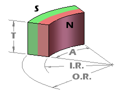 Arc magnet orientation example for permanent magnet rotors.
Production Risks to Control
Incorrect magnetization direction can create torque loss, unstable sensor output, increased cogging torque, high vibration or complete assembly failure. The risk increases when magnets are small, pole pitch is tight, the rotor uses many segments, or magnetization is performed after assembly.
Ningbo Vanguard Technologies Co., Ltd supports magnetization review for custom magnets and magnetic assemblies, including drawing optimization, magnetizing fixture feasibility, polarity inspection and prototype-to-production transfer.
Information Needed for Fast Quotation
| RFQ Information | Why It Matters | Example |
|---|---|---|
| Magnet drawing | Defines shape, tolerance, coating and feasible magnetization direction | Arc segment, ring, cylinder, block or custom magnet |
| Required magnetization | Determines magnetizing fixture and inspection method | Axial, radial, diametric, multipole or custom pattern |
| Application structure | Confirms whether flux direction matches motor or assembly topology | Rotor, stator, coupling, encoder, sensor or linear track |
| Magnet material and grade | Controls magnetic output, temperature margin and coercivity | NdFeB N48H, SmCo 2:17, ferrite, bonded magnet |
| Inspection requirement | Prevents polarity error and production drift | Surface field, flux, polarity map, waveform or assembly test |
FAQ
Can any magnet shape be radially magnetized?
No. Radial magnetization depends on magnet geometry, material, size and magnetizing fixture capability. Large rings, thin arcs and high-coercivity grades need feasibility review before production.
What is the difference between radial and diametric magnetization?
Radial magnetization points through the radius of a ring or arc. Diametric magnetization creates north and south poles across the diameter of a cylinder or ring.
When should multipole magnetization be used?
Multipole magnetization is used when several alternating poles are required on one ring, disc or track, such as sensor rings, encoder magnets, stepper motors and compact fan rotors.
Can Vanguard help define magnetization direction from a motor design?
Yes. We can review drawings, magnetic circuit requirements, pole layout, magnetizing fixture feasibility and inspection standards for prototype and production programs.
Need custom magnetization support for motor magnets?
Send your magnet drawing, motor topology, pole count, operating temperature and inspection requirement. Our engineering team can review magnetization direction, material selection and production feasibility.
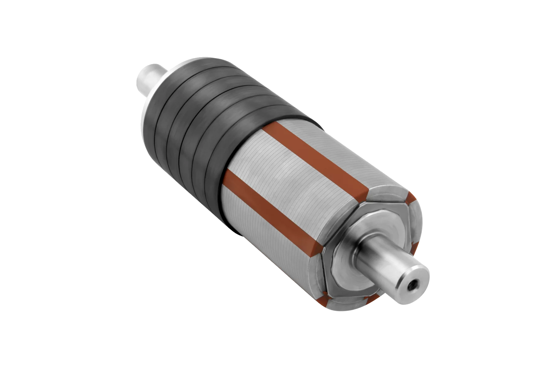
Image sources: hero image from VAC Magnet Assemblies page; multipole ring gallery images from Stanford Magnets multipole ring technology page; arc magnetization image from EPI Magnets magnetization direction guide. Images were selected from visible no-watermark web results. For formal commercial publishing, please confirm usage rights with the source owners or replace them with company-owned product photography.
0
Comments
Leave a Comment
Your email address will not be published. Required fields are marked *
Name can't be empty
Email error!
Message can't be empty
😍
😜
😳
😌
😄
😘
😝
😒
😃
😚
😚
😛
😟
😧
😀
😉
😓
😱
😤
😣
😂
😥
😩
😠
😢
😭
😰
😨
😡
😆
😪
😅
😐
😇
😋
😴
👿
😕
😏
😷
😵
😟
😮
😯
😑
👧
👴
😧
😬
😾
👶
👱
👵
👸
🙀
👺
👦
👩
👨
😽
😿
🙈
💩
💥
💤
😼
😹
🙉
🔥
✨
💦
👎
✌
👆
👈
💪
💹
👍
👊
💴
💶
💷
💸
👉
💵
🙏
🌎
🏧
👏
💳
👇
💑
🙆
🙅
💁
👫
👭
🙎
🙇
👑
👔
Submit Comment
Most Popular
-
 Jul 21, 2026Top 8 Motor Laminations Manufacturers in the USA 2026
 -
 Jul 21, 2026Top 10 Electrical Lamination Manufacturers in the USA 2026
 -
 Jul 10, 2026Top 10 Custom Magnetic Assemblies Factory in the USA 2026
 -
 Jul 22, 2026Top 5 Rotor Assembly Manufacturers in the USA 2026


Laster Blogs


Set A Consultation Today
Name can't be empty
Email error!
Send Your Message
*We respect your confidentiality and all
information are protected.